Summary view
Every row of the Summary view — how the per-plant sheet is laid out, the banners above it, what each row reports, and when a row reads — or 0.
The Summary view is the per-plant sheet turned on its side: a Metric column on the left, one column per plant — one per plant boundary in your file — and a Total column when there are two or more plants. The rows are grouped under SITE · ARRAY · ELECTRICAL · CABLES · ENERGY. It is the second of the five view tabs across the top of the right side (Ctrl+2), and before a layout exists it reads "Generate a layout to see the per-plant summary here." See Views.
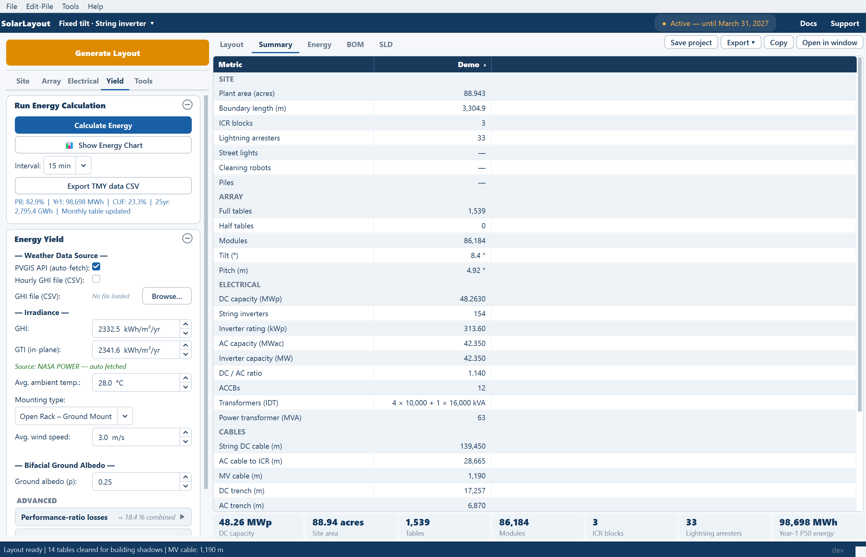
How the view is laid out
- Plant column headers carry the plant's name followed by ›. Clicking one shows that plant on the Layout view.
- Total appears only with two or more plants and sums every plant. See Multi-plot sites.
- Two tools sit right of the view tabs. Copy puts the whole sheet on the clipboard as tab-separated text ("Copied. Paste into Excel or a document."). Open in window opens SolarLayout — Summary, a separate window that follows the layout as it changes, with two tabs: Summary and Monthly energy (Year 1), the second enabled once energy exists.
- The Plant totals row of the Layers ▾ popover governs the row of plant chips under every view, not this sheet. Clicking any chip opens the Summary view; the energy chip opens the Energy view.
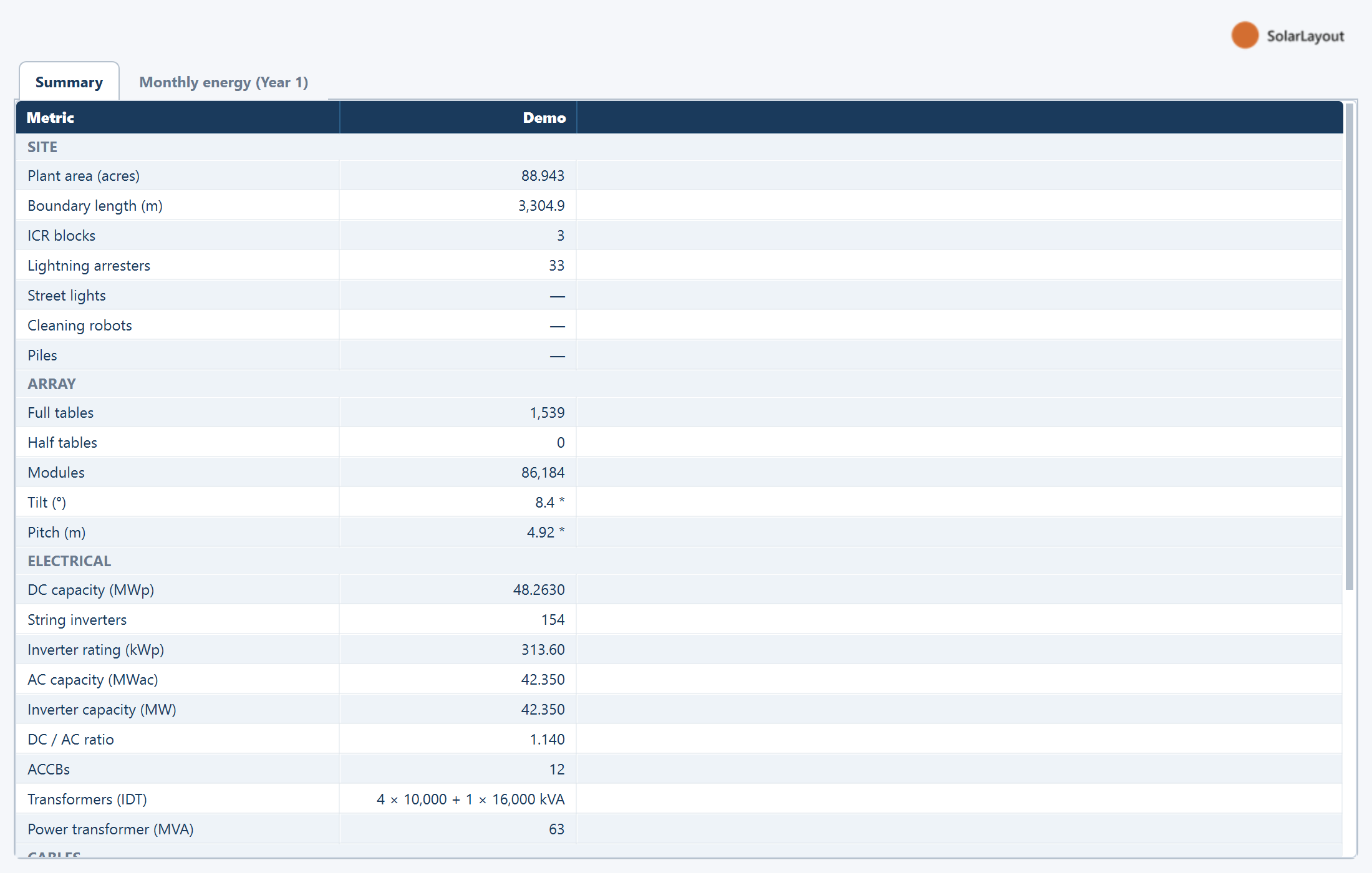
The banners above the sheet
Two banners can sit above the figures. Neither appears when it does not apply.
The out-of-date banner. When any input has changed since the layout was generated, the sheet still shows the last run's figures, greyed, under a banner that names each change — for example Out of date. These figures are from the last run, and 2 inputs have changed since: Module wattage 610.0 Wp → 700.0 Wp, Soiling losses 2.0 % → 3.0 %. Regenerate the layout to update them. Copy is disabled meanwhile, with the tooltip "Inputs changed since the last run. Regenerate first.", and the Out of date chip heads the plant chips. Change the values back, or click Regenerate Layout, and the banner goes. The SolarLayout — Summary window carries the same banner. See Out-of-date results.
The design warnings banner. When the last run's design falls outside a design rule — a control room over its rating or not placed, a trench outside the plant or under a table, a feeder over one run or over its voltage-drop limit, the plant's LV drop over budget, a DC trunk too long — a warning-tone banner titled "1 design warning" or "2 design warnings" reads "The layout is complete, but this falls outside the design rules. The PDF summary and the BOM carry it too.", then lists one line per warning, led by the plot name on a multi-plot site. A Design warnings chip carrying the count sits at the head of the plant chips, after the Out of date chip when both show. A warning never blocks anything, and the banner clears when the design is clean again. The trench, feeder and drop checks need Calculate cables on. What each check means and how to clear it is on Design warnings.
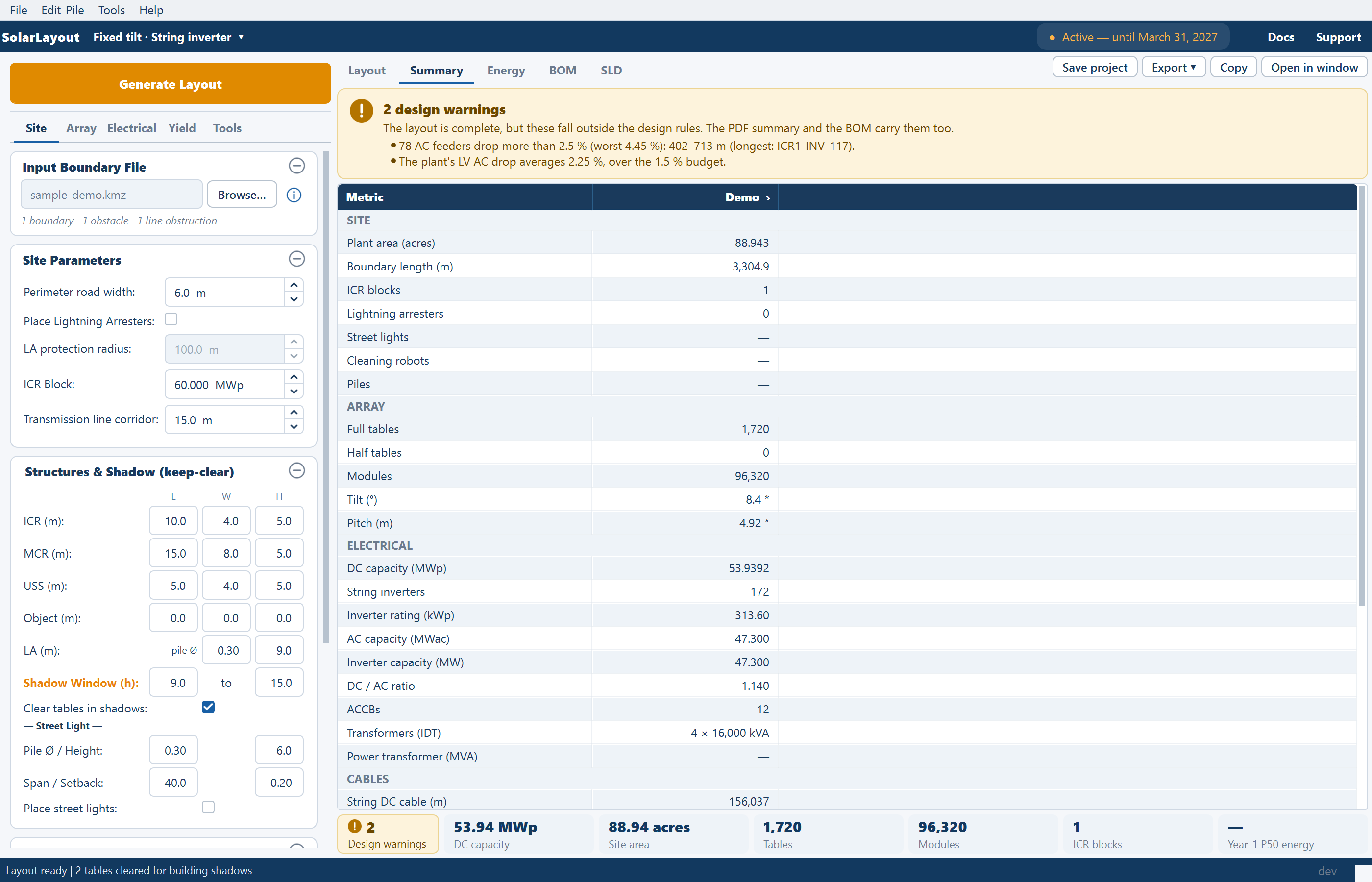
The design warnings stay on the sheet, greyed, while the layout is out of date. They are not in the SolarLayout — Summary window or in what Copy puts on the clipboard.
Reading the sheet
A trailing asterisk means the value was calculated, not entered. Tilt
and Pitch carry a * when the layout derived them from the site latitude
rather than taking an override from you. It appears on fixed tilt only. No
asterisk on those two rows means you supplied the number yourself — the fastest
way to check that an override you ticked took effect. See
Spacing and tilt.
A dash means not computed. A — is not a zero and not an error. The
commonest case is the whole CABLES group when Calculate cables was left off:
the inverter and box counts are still computed, and every cable row reads —.
The ENERGY rows read — until energy has been calculated.
Whole numbers of four or more digits get thousands separators on screen.
SITE
| Row | What it means | Reads — or 0 when |
|---|---|---|
| Plant area (acres) | The plant's gross boundary area, taken before the perimeter road setback | Never — filled by the layout run |
| Boundary length (m) | The perimeter of the plant boundary | Never |
| ICR blocks | Inverter control rooms placed. The number needed is counted per separate piece of land: each piece's capacity ÷ ICR Block, rounded up. A room the plot needs but could not fit is reported as the design warning ICR not placed | Never |
| Lightning arresters | Arresters placed | 0 unless Place Lightning Arresters was on, or you added arresters in Sketch Mode |
| Street lights | Street light poles placed along the perimeter | 0 unless Place street lights was on |
| Cleaning robots | The fleet the cleaning study sized | Empty until Robotic Module Cleaning has been run |
| Piles | Each unit's own piles, summed: the full pattern on every full table or tracker, the half pattern on every half unit. Counted whether or not the pile overlay is on | — until a pile pattern exists |
Plant area is the site's area, not the array's. It is the area enclosed by the whole boundary polygon, before the perimeter road setback and before any obstruction or terrain exclusion — so it does not fall as exclusions grow. Add an obstruction, tighten the slope limits or widen the perimeter road and the capacity drops while this row stays exactly where it was.
ICR blocks can exceed the plant capacity ÷ ICR Block. Tables separated from the rest by a gap of more than 300 m form a separate piece of land, and each piece gets its own rooms however small it is. The count also follows the capacity left after the rooms and the building-shadow keep-clear are cleared, so road width, obstructions and the shadow window can change it. See Inverter control rooms; the per-block figures are in the ICR block window, see ICR blocks.
Piles counts every unit's own pattern. A half table carries the half pattern — derived from the full one, or your own — so a plant with half-table infill counts fewer piles there than on its full tables. See Piles.
ARRAY
| Row | What it means | Reads — or 0 when |
|---|---|---|
| Full tables / Full trackers | Full MMS tables, or full tracker units, placed | Never |
| Half tables / Half trackers | Half units placed | 0 unless Add half tables / Add half trackers was on, or you placed them in Sketch Mode |
| Modules | Modules placed across the plant, full units plus half units | Never |
| Tilt (°) / Max tracking angle (°) | The fixed tilt the layout used, or the tracker's rotation limit — a tracker has no single tilt. May carry a * | Never |
| Pitch (m) | The row spacing the layout used. May carry a * | Never |
The first word of each row follows the mounting type; the position in the sheet does not move.
ELECTRICAL
The inverter rows are a different set in each design, not the same rows relabelled. The rows after them are common to both, except ACCBs, which a central design does not have.
| Row | What it means |
|---|---|
| DC capacity (MWp) | Plant DC capacity: the placed modules multiplied by the wattage |
| String inverters | String inverters placed |
| Inverter rating (kWp) | The DC capacity one string inverter carries |
Then, in both designs:
| Row | What it means | Reads — when |
|---|---|---|
| AC capacity (MWac) | The AC capacity the plant is sized against: the target of a Simulation with AC Capacity when one was run, otherwise the inverter capacity: the inverter file's AC power rating × the inverter count | No inverter file has been loaded |
| Inverter capacity (MW) | The installed inverter capacity | No inverter file has been loaded |
| DC / AC ratio | DC capacity divided by AC capacity. The design overload limit is 1.5 for string inverters and 1.4 for central inverters | No inverter file has been loaded |
| ACCBs (string design only) | AC combiner boxes, from the ACCB & Transformer card: each ICR block's inverters ÷ Inverters per ACCB, max, rounded up | Before inverters are placed |
| Transformers (IDT) | The inverter duty transformers and their ratings, e.g. "4 × 16,000 kVA" or "2 × 12,500 + 2 × 16,000 kVA". Without an inverter file only the count, "4 · rating needs OND"; a transformer whose load fits no listed rating reads "4 · 1 with no listed rating" | Before inverters are placed |
| Power transformer (MVA) | The whole site's power transformer at the main control room, e.g. "63" or "2 × 80". Shown in the column of the plot that holds the MCR and in Total; needs OND when there is an MCR but no inverter file | No MCR is placed; in every other plot's column; before inverters are placed |
Total sums the ACCBs and the transformers. The three grouping rows follow the ACCB & Transformer card at once — an edit there regroups the plant and updates them without a Generate. See ACCB and transformers.
Comparing a string design against a central design therefore means comparing different rows. Read DC capacity, ICR blocks, Transformers (IDT) and the CABLES group instead — those are common to both.
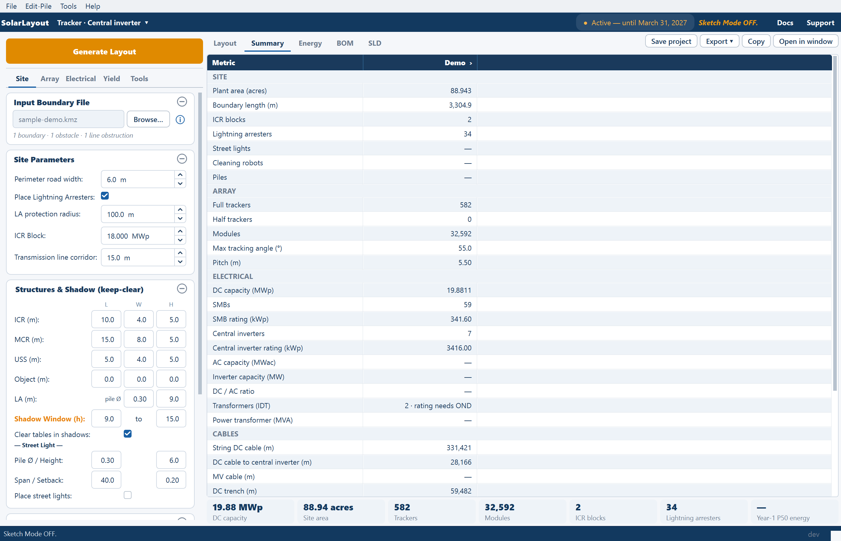
CABLES
Six rows in metres, answering two different questions. The first three are conductor to procure; the last three are trench to dig. Mixing them up over-orders cable or under-digs trench.
| Row | What it means | Reads — when |
|---|---|---|
| String DC cable (m) | Conductor from the tables to the string inverter or the SMB, counted twice for the positive and negative conductors | Calculate cables was off |
| AC cable to ICR (m) (string) / DC cable to central inverter (m) (central) | AC from each inverter to the control room it is assigned to, counted once as a three-phase run — or the DC trunk from each box to the control room, counted twice. There is no AC leg in a central design, because the central inverter sits inside the building | Calculate cables was off |
| MV cable (m) | Medium-voltage conductor from the control rooms to the main control room | No MCR placed, or the layout not generated again with cables on since placing it |
| DC trench (m) | Trench length for the string DC cables | Calculate cables was off |
| AC trench (m) | Trench length for the second leg | Calculate cables was off |
| MV trench (m) | Trench length for the medium-voltage run | As MV cable (m) |
Each inverter is assigned to the nearest control room along the plant that still has room within its rating, not merely the nearest building. How each route is chosen is on Cable routing.
A trench total is the de-duplicated path length per cable type, so a stretch several cables share is counted once. The trench figures are therefore the smaller ones, and the gap widens as the plant grows, because more cables share each corridor near the control rooms; medium-voltage routes in particular merge nearby control rooms into one trunk.
Because one second-leg figure is counted once and the other twice, the two are not comparable as a cable quantity even on the same plant.
On a plot of more than 30 000 tables, the DC trench is measured on a drawn sample of the DC cabling and scaled to every table. The bill of materials, the PDF summary page and the Word report mark that figure "(est.)".
Drawing an obstruction on the Tools tab — and Undo Last, Clear All or dragging a control room — re-places the inverters and, with cables on, re-measures String DC cable (m) and the second-leg row. The trench rows keep their previous figures until the next full cable run: a Generate, or leaving Sketch Mode after a change. Generate again before quoting trench lengths.
ENERGY
All five rows are empty until energy has been calculated, and every Generate that replaces the layout clears them again. See How yield is calculated.
| Row | What it means |
|---|---|
| P50 energy, year 1 (MWh) | Year-one energy at the first exceedance probability |
| P75 energy, year 1 (MWh) | Year-one energy at the second exceedance probability |
| P90 energy, year 1 (MWh) | Year-one energy at the third exceedance probability |
| CUF (%) | Capacity utilisation factor: year-one energy divided by capacity in kWp × 8760 hours, as a percentage |
| P50 energy, 25 years (MWh) | The lifetime total — see below |
The three P rows are named from the exceedance probabilities you set, not fixed. On the shipped defaults of 50 %, 75 % and 90 % they read as above; change any of the three fields under Uncertainty & exceedance and the row name changes with it. Reading a sheet someone else produced, check the row names before quoting a number.
"P50 energy, 25 years" does not report 25 years. The figure is the cumulative energy over years 1 to Plant lifetime, after degradation, at the first exceedance probability — and the row name does not follow the lifetime setting. Plant lifetime ships at 30 years, so on shipped settings a row named "25 years" carries a 30-year total, and raising or lowering the lifetime moves the figure while the name stands still.
Do not quote the lifetime row by its name. Read Plant lifetime and the first exceedance probability off the Yield tab and state both alongside the figure, or the number will be attributed to a period it was never computed over. How the figures are derived is on Lifetime and P-values.
Where the same figures appear elsewhere
The sheet is not the only place these numbers surface, and the other places carry a subset rather than a different calculation.
| Destination | What it carries |
|---|---|
| The plant chips under every view | DC capacity, site area, plants (multi-plot only), tables or trackers, modules, ICR blocks, lightning arresters (when placed) and year-one P50 energy, led by the Out of date and Design warnings chips when they apply. Water-body results are left out of the totals |
| The ICR block window | One block's figures — area, tables, modules, inverters, ACCBs, transformer and its load, capacities, DC/AC ratio, cable lengths, arresters and piles. Energy is not split per block |
| The Yield tab's status line | After a run: PR, year-one energy, CUF and the lifetime total |
| The Word report | The Results & Analysis — Output section and the Design Summary annexure, with its design warnings block; the energy sections only when energy was calculated. See Project report |
| The cable schedule (Excel) | One sheet per ICR block: the DC strings, the AC feeders or DC trunks, and the collection runs from each combiner box or central inverter to its transformer and on to the main control room. See The cable schedule |
| The TMY data CSV | The GHI, in-plane irradiance and energy time series the ENERGY rows are built from, at the interval you choose. See Time series |
| The Google Earth file | A summary placemark per plant carrying capacity in MWp, area in acres, pitch and table count, plus an Overall Summary folder aggregating every boundary. See KMZ export |
| The bill of materials | Quantities computed from the same placed counts and the same grouping, including the cleaning fleet once you have asked for one, and a Check: remark on the rows a design warning qualifies. See Bill of materials |
Where to go next
Every parameter and its default
The complete input reference — every card on the five stage tabs and every study window, each field's shipped default, its range, and what it changes.
Design warnings
Every design warning — what triggers it, the text the application shows, where it appears, and what to change to clear it.