ACCB and transformers
How the ACCB & Transformer card groups each ICR block's inverters onto combiner boxes and transformers, and sizes the power transformer.
The ACCB & Transformer card, the second card on the Electrical tab, holds the rules that group the plant's AC equipment. Inside every ICR block — one inverter control room and the tables wired to it — it gathers the string inverters onto AC combiner boxes (ACCBs), the combiner boxes onto inverter duty transformers (IDTs), and it sizes the power transformer at the main control room for the plant as a whole. The counts, the transformer loads and the ratings it produces are the ones the Summary view, the bill of materials, the single-line diagram, the cable schedule and the ICR block window all print, so they agree with one another.
The card changes with the inverter topology chosen at launch. In a central-inverter design it is titled Transformer: there are no combiner boxes, and the central inverters in each control room land on the transformers directly. See Choosing a design mode.
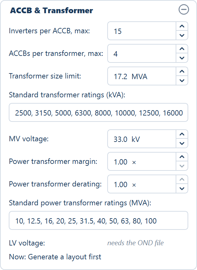
The fields
Top to bottom, as the card shows them. Every row except the last two is yours to set.
| Field | Default | Range | What it does |
|---|---|---|---|
| Inverters per ACCB, max (string design) | 15 | 1–60 | The most string inverters on one AC combiner box. Each ICR block gets its own ACCBs, with the inverters shared evenly between them |
| ACCBs per transformer, max (string design) | 4 | 1–12 | The most ACCBs on one transformer. Each takes one low-voltage winding |
| Central inverters per transformer, max (central design, in place of the two rows above) | 4 | 1–12 | The most central inverters on one transformer. Each takes one low-voltage winding |
| Transformer size limit | 17.2 MVA | 0.5–100.0 MVA | The largest transformer allowed. A block whose load is bigger gets more transformers. Never above the largest listed rating |
| Standard transformer ratings (kVA) | 2500, 3150, 5000, 6300, 8000, 10000, 12500, 16000 | — | The ratings an inverter duty transformer can take. Each transformer takes the smallest one at or above its load |
| MV voltage | 33.0 kV | 0.4–400.0 kV | The transformers' medium-voltage side, printed with their ratings (see MV voltage) |
| Power transformer margin | 1.00 × | 1.00–3.00 × | Multiplies the plant's maximum AC output when the power transformer is sized |
| Power transformer derating | 1.00 × | 0.50–1.00 × | Divides it. Set below 1.00 for a site above about 40 °C ambient or 1,000 m altitude, so the same load needs a higher rating |
| Standard power transformer ratings (MVA) | 10, 12.5, 16, 20, 25, 31.5, 40, 50, 63, 80, 100 | — | The ratings the power transformer can take. Above the largest, as many transformers as the need requires |
| LV voltage | needs the OND file | read-only | The transformers' low-voltage side, read from the inverter file |
| (the answer line) | Now: Generate a layout first | read-only | What the rules produce for the current layout |
The margin and the derating move in steps of 0.05. The two rating lists are text fields, under their captions, across the full width of the card.
Entering a rating list
A rating list is read when you finish editing it — press Enter or leave the
field. Separate the ratings with commas, semicolons or spaces, in any order:
the list is sorted, duplicates are dropped, and it is written back tidily, such
as 2500, 5000.
A list the application cannot use is not applied. The previous ratings stay in force, and a hint under the field says why and which ratings are still being used:
| Entered | Hint |
|---|---|
| Nothing | List at least one rating. Keeping 2500, 5000. |
| A word or symbol | “x” is not a number. Keeping … |
| Zero or a negative figure | x is not a positive rating. Keeping … |
The largest rating in the list also caps the transformer size limit — see How a block is grouped.
The LV voltage line
The low-voltage side is not an input. It reads needs the OND file until an inverter file is loaded on the inverter card, then the file's output voltage, for example 800 V · from the OND. See Inverter settings.
The answer line
The last line of the card, prefixed Now:, shows what the rules produce for the layout on screen, and updates as you change them.
| State | What the line reads |
|---|---|
| No layout yet | Now: Generate a layout first |
| String design, inverter file loaded | Now: 12 ACCBs · 4 transformers: 4 × 16,000 kVA, or with mixed ratings … : 2 × 12,500 + 2 × 16,000 kVA |
| No inverter file | Now: 12 ACCBs · 4 transformers · ratings need the OND file |
| Central design | Now: 16 central inverters · 4 transformers: …, or … · ratings need the OND file |
| A transformer's load fits no listed rating within the limit | the ratings, then · 1 with no listed rating (the count of such transformers) |
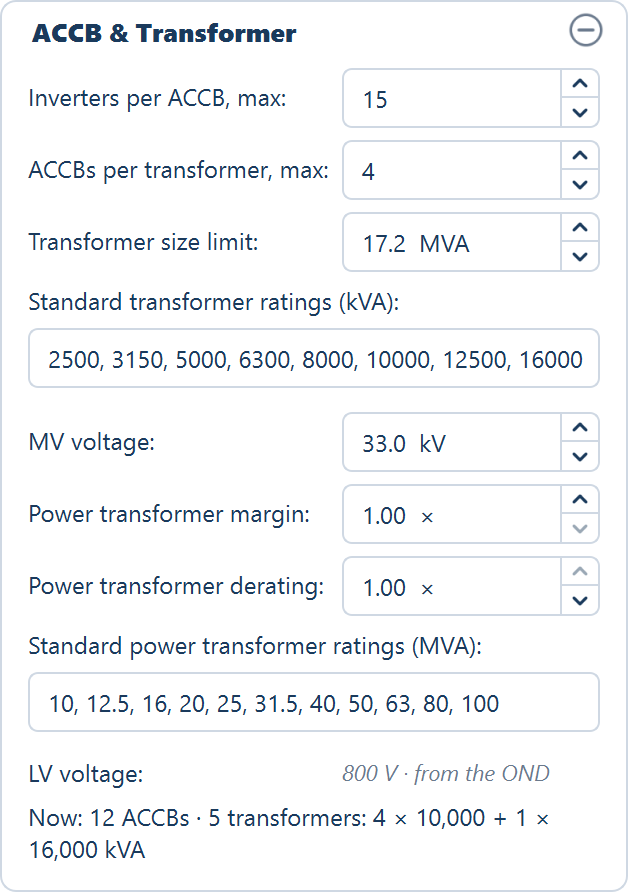
The answer line covers the ACCBs and the inverter duty transformers only. The power transformer's figure is in the Summary view and the bill of materials.
How a block is grouped
The grouping is made per ICR block: one inverter control room and the tables wired to it through their inverters or string monitoring boxes. No combiner box and no transformer is shared between two blocks. See ICR blocks.
For each block:
| Quantity | Rule |
|---|---|
| ACCBs (string design) | The block's inverters ÷ Inverters per ACCB, max, rounded up. The inverters are shared out in order so that no two ACCBs differ by more than one inverter |
| Central inverters (central design) | The block's SMBs ÷ Max SMB per Central Inverter, rounded up — at least one and at most four per control room. After a Simulation with AC capacity they are topped up to the study's unit count |
| Transformers | The larger of: the feeders (ACCBs or central inverters) ÷ the per-transformer maximum, rounded up; and, with an inverter file, the block's load ÷ the size limit, rounded up. Never more transformers than feeders. The feeders are shared out in order, and a transformer is added while any one is still over the limit |
| The limit | Transformer size limit, but never above the largest listed rating. With the defaults that is 16,000 kVA, not 17.2 MVA |
| Transformer load | The sum of the inverter file's maximum AC output over every inverter (or central inverter) on that transformer |
| Transformer rating | The smallest listed rating at or above the load and no larger than the limit. When none fits, the transformer has no rating and is counted as with no listed rating |
| Windings | One low-voltage winding per ACCB or central inverter on the transformer, plus one |
| Voltages | Low voltage from the inverter file; medium voltage from MV voltage |
A worked example
A string-design block with 60 inverters, the card at its defaults, and an inverter file giving 300 kVA maximum output per inverter:
- ACCBs: 60 ÷ 15 = 4 ACCBs of 15 inverters each.
- Transformers by feeders: 4 ACCBs ÷ 4 per transformer = 1.
- Transformers by load: 60 × 300 kVA = 18,000 kVA, over the 16,000 kVA limit, so 18,000 ÷ 16,000 rounded up = 2 transformers, the larger figure.
- Each transformer carries 2 ACCBs — 30 inverters, 9,000 kVA — and takes the smallest listed rating at or above that: 10,000 kVA, with three windings.
With 53 inverters instead, the load is 15,900 kVA: one transformer carrying all four ACCBs, rated 16,000 kVA, with five windings.
Without an inverter file
With no inverter file loaded the card still groups — the ACCB, central inverter and transformer counts are made — but there is no load, so the transformers carry no rating and no low-voltage figure. The outputs say so: rating needs OND in the Summary view and the ICR block window, LV needs OND on the single-line diagram. Load the inverter file on the inverter card to fill them in.
The power transformer
The power transformer steps the whole plant's output up at the main control room. It is sized only when three things are true: a plot holds a main control room, an inverter file is loaded, and the plant has been grouped. Place the main control room from the Tools tab — see Site equipment.
It is sized from every inverter in the plant (every central inverter, in a central-inverter design), including the plots that feed the main control room through their own unit substation:
Add up the maximum AC output
Every inverter at the inverter file's maximum AC output, in MVA.
Apply the margin and the derating
Multiply by Power transformer margin and divide by Power transformer derating. The result is the plant's need.
Pick the ratings
If the need fits under the largest listed rating, one transformer takes the smallest listed rating at or above it. If not, the need is split across as many transformers as the largest rating requires, each taking the smallest listed rating at or above its share.
The result reads as a rating in MVA — 63, or 2 × 80 for two machines. With a
main control room but no inverter file it reads needs OND; without a main
control room there is no power transformer and the figure reads —. The bill
of materials prints the basis as its remark, for example Σ PMaxOut 58.1 MVA ×
margin 1 ÷ derating 1 = 58.1 MVA → next listed rating, which with the default
ratings gives 63.
The margin ships at 1.00. Rounding up to the next listed rating already leaves headroom; raise the margin only when your own practice asks for more.
What changing the card does
The card acts on the layout already on screen. You do not generate again.
- Every change regroups every plot at once — each change of a number, and each rating list accepted. Nothing moves: no table, inverter or cable is placed or routed again. Before the first layout a change simply waits: the next Generate Layout groups the plant with it.
- The answer line and the Summary view refresh straight away.
- Any open ICR block windows close. Open the block again to see the new grouping.
- The layout does not go out of date. The card's fields are not layout inputs, so no amber marks appear and every export stays available. Loading an inverter file is different: it regroups in the same way, but it does mark the layout out of date, because the inverter file is an input to the run. See Out-of-date results.
- The bill of materials is rebuilt the next time you open the BOM view. The list is recomputed from the layout at that moment.
- A single-line diagram already on the sheet is not redrawn. Choose Automatic again in the SLD view to rebuild it from the new grouping. See Building a diagram from the plant.
The rebuild of the bill of materials after a change on this card discards any edits you made to the list, without asking — added rows, corrected descriptions, typed remarks and a template put in place of the computed list. Settle the grouping before you edit the list, and make your edits to the list last. See Bill of materials.
The card's rules are saved in the project file and come back when it is reopened; the grouping itself returns with the saved layout, so nothing is regrouped on opening. See Projects.
Where the grouping appears
Every output reads the same grouping, so a count in one agrees with the count in the others.
| Where | What it shows |
|---|---|
| Summary view, ELECTRICAL group | ACCBs (string design only), Transformers (IDT) — such as 4 × 16,000 kVA, 4 · rating needs OND or 4 · 1 with no listed rating — and Power transformer (MVA), shown on the plot holding the main control room and in the Total column. All three read — before a layout. See Summary view |
| ICR block window | ACCBs or Central inverters, Transformer (such as 1 × 16,000 kVA · 4-winding) and Transformer load (such as 13,200 kVA · 33 / 0.8 kV) for that block; the same rows print in the ICR-block PDF and DXF. See ICR blocks |
| Bill of materials | ACCB (AC Combiner Box), Inverter Duty Transformer (IDT) and Power Transformer, with remarks that follow the card. See Bill of materials |
| Single-line diagram | The automatic build's ACCB and transformer counts, ratings, windings and voltages. See Building a diagram from the plant |
| Cable schedule | The collection table: each ACCB or central inverter to its transformer, and on to the main control room. See The cable schedule |
MV voltage
MV voltage is printed wherever a transformer's voltages are: the single-line diagram's transformer, switchgear and grid labels, the bill of materials' IDT remark, and the ICR block window's Transformer load row. It does not reach the cable schedule, which sizes and labels its medium-voltage runs at 33 kV whatever the card says.
Where to go next
Inverter settings
Strings per inverter or SMB, and the inverter file the loads and the LV voltage come from
Building a diagram from the plant
How the automatic single-line diagram draws this grouping
Bill of materials
The ACCB, IDT and power transformer rows and their remarks
ICR blocks
The blocks the grouping is made in, and the window that reports each one
Inverter settings
How many strings feed one inverter or string monitoring box, what a manufacturer inverter file changes, and where the AC figures land in the Summary view.
Cables
The Cables card on the Electrical tab — whether cable runs are routed and measured, and the three allowances added to the DC string-cable total.