Site parameters
The plant-wide settings — perimeter road width, lightning arrester coverage, the capacity one control room serves, and transmission line corridors.
Site Parameters holds the settings that apply to the plant as a whole rather than to an individual table: how much ground is kept clear around the fence, whether lightning arresters are placed and how far apart, how much capacity one control room serves, and how wide a strip is cleared either side of a transmission line.
Two of them — the perimeter road width and the transmission line corridor — decide how much ground is available before a single table is placed. The rest decide what equipment is then placed on the ground that remains.
The card is the second one on the Site tab, between the Input Boundary File card and the two keep-clear cards, Structures & Shadow and Topography.
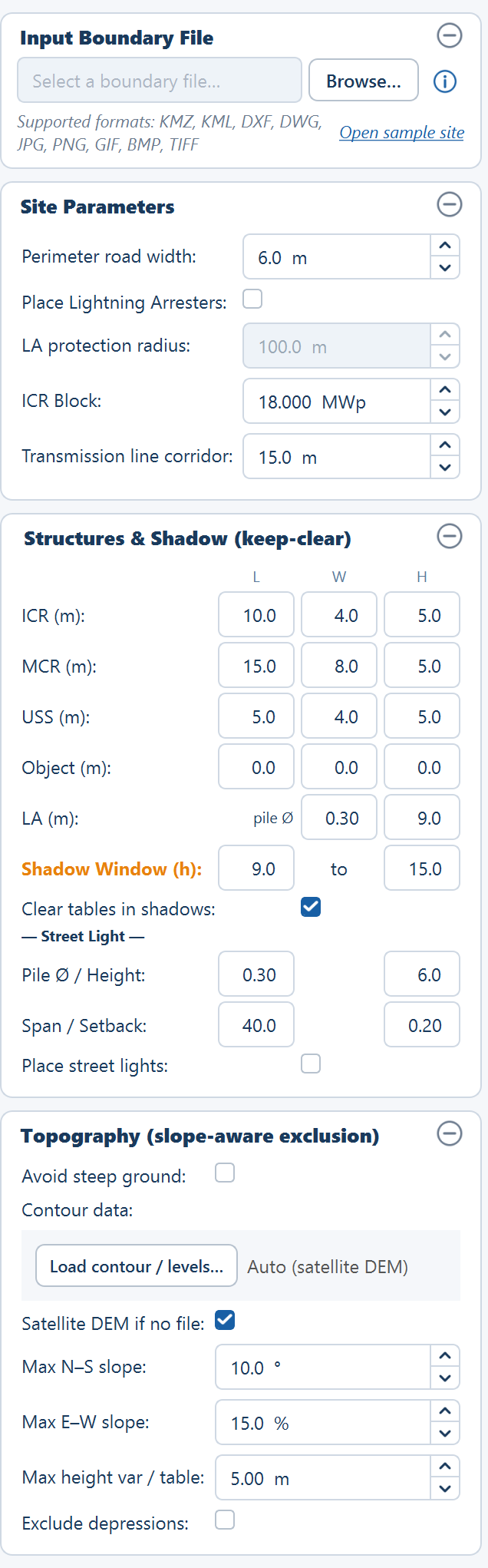
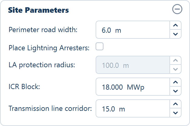
At a glance
| Field | Default | Range | What it does |
|---|---|---|---|
| Perimeter road width | 6.0 m | 0.0–50.0 m | Shrinks the plant boundary inward by this distance. Nothing is placed in the band that is left. |
| Place Lightning Arresters | off | — | When on, arresters are placed on a coverage grid and the tables they overlap are cleared. |
| LA protection radius | 100.0 m | 10.0–500.0 m | The area one arrester is taken to protect, and the spacing of the grid they sit on. Enabled only when arresters are on. |
| ICR Block | 18.000 MWp | 0.1–500.0 MWp | The DC capacity one inverter control room serves. Sets how many control rooms each piece of land gets. |
| Transmission line corridor | 15.0 m per side | 0.0–500.0 m | The setback applied to each side of a line feature, so the cleared strip is twice this figure. |
Perimeter road width
The plant boundary is shrunk inward by the perimeter road width to give the usable area — the ground the layout is allowed to occupy. Obstructions and terrain exclusions are then subtracted from it, and a table or tracker unit is placed only where it fits entirely inside what is left.
So this is not a road you design here. It is a setback, kept clear of modules around the whole plant, wide enough to take the internal ring road, the fence line and the working space a construction crew needs to get plant and cable drums around the perimeter. Widen it and every edge of the plant pulls inward at once; the capacity you lose is roughly the perimeter length multiplied by the extra width.
The band is computed once from the boundary and reused everywhere the plant is drawn — the plot on screen, the report, the Google Earth file and the CAD drawing — so the road you see on the screen is the road that reaches the contractor.
Entering 0 leaves no band at all, and tables are placed right up to the boundary. That is worth doing only when the boundary you supplied already excludes the road.
DC string cables are kept off the perimeter road band. AC feeders, and the DC trunks of a central-inverter design, are held inside the plant boundary wherever a route exists; a run that cannot be kept inside is reported as a design warning rather than hidden. See Cable routing.
Place Lightning Arresters
Off by default. Lightning arresters (LA) are the masts that carry the plant's lightning protection over the array.
With the option off, no arresters are placed and the tables fill the whole usable area. Nothing is reserved for them, and the plant's capacity is the capacity of a fully packed field.
With the option on, arresters are placed on a square coverage grid once the tables are down, and every table overlapping an arrester's keep-clear footprint is removed. On a fixed-tilt plant that footprint is a rectangle of 30 m east–west by 7 m north–south, which is why the arrester count has a visible effect on capacity. On a tracker plant the arrester is a 1 m by 1 m pole marker snapped into the gap between tracker columns, and no tracker units are removed at all.
Arresters only ever sit inside the usable area, so the grid never puts a mast in the perimeter road band, in a water body or on excluded ground.
Because arresters cost capacity on a fixed-tilt plant, the usual sequence is to generate the layout with the option off, agree the field, and then turn it on for the run you issue. The tick and the radius are both kept in the project file.
You can also leave it off and add arresters one at a time by hand in Sketch Mode — the plant totals are recomputed when you leave it, so a hand-placed arrester clears tables and changes the capacity exactly as an automatic one does.
The placed count appears on the Lightning arresters row of the Summary view and, once any are placed, on a Lightning arresters chip in the row of plant chips under the plot. The arresters themselves are hidden on the plot until you switch the Lightning arresters row on in the Layers ▾ popover. Lightning arresters covers the grid, the coverage circles and the footprints in full.
LA protection radius
Enabled only when Place Lightning Arresters is ticked.
This one field does two jobs at once:
- It is the radius of the circular area one arrester is taken to protect, measured from the mast.
- It is the spacing of the square grid the arresters are placed on.
Because the two are the same number, every point inside the array is within one radius of an arrester, and neighbouring protection circles always overlap. The grid alone can leave a table at the edge of the array uncovered, so after the grid pass any table whose centre lies beyond the radius from every placed arrester gets an extra arrester at the nearest valid position.
The consequence of tying spacing to radius is that the radius is the only lever on the arrester count, and it is a strong one: doubling it doubles the grid spacing in both directions, so roughly a quarter as many masts are placed. Halving it does the reverse. On a fixed-tilt plant that change in count feeds straight through to lost tables, because each arrester clears its own footprint.
Raising the radius does not make the protection cheaper — it asserts that one mast protects further. The value has to be justified for your mast height, your array geometry and the local lightning density before you take the reduced count into a design.
ICR Block
An inverter control room (ICR) is the building a block of the array is collected into — in a central-inverter design it also houses the central inverters. ICR Block is the DC capacity, in MWp, that one such room serves. The field shows three decimals — 18.000 MWp as shipped — because the AC-capacity study can write a block capacity into it to the kilowatt.
The count follows from it, for each separate piece of land. Tables linked by gaps of no more than 300 m are one piece; internal roads, corridors and setbacks never split one. Each piece gets its capacity divided by the block size, rounded up to the next whole room, with a half table counted at half a table's capacity, and the plant's count is the sum over its pieces:
- On a site in one piece, that is the plant's DC capacity divided by the block size, rounded up. A plant whose capacity exceeds a multiple of the block size by any margin at all gets another room.
- On a site in several distant pieces it can be more, because each piece — even a small one — gets a room of its own.
You cannot set the count directly: it follows the capacity actually placed and how the land splits.
Where the rooms go is not a grid. The tables of each piece are divided into exactly as many compact groups as the piece has rooms, each carrying close to the same capacity, and a control room is put at the centre of each group — so every group of tables surrounds its own room rather than being cabled across the site to a distant one. An extra room therefore makes every block a little smaller rather than adding one small block. Each room must fit entirely inside the usable area, and any table overlapping its footprint is removed. Because that removal reduces the plant's capacity, the required number of rooms is then re-checked against the reduced figure — and, on a fixed-tilt plant, once more after the building-shadow keep-clear, when it can only fall.
Choosing the block size is a cabling trade-off:
| Smaller block | Larger block |
|---|---|
| More control rooms, more buildings, more switchgear | Fewer buildings, less switchgear |
| Shorter AC or DC runs from the array to each room | Longer runs, heavier conductor, higher cable loss |
| More ground lost to building footprints | Less ground lost |
| More medium-voltage circuits back to the main control room | Fewer, larger circuits |
In a central-inverter design there is a second constraint worth knowing before you set the block: a maximum of 4 central inverters are housed in one control room building. See Inverter settings.
The footprint and height of the room itself are not set here — they are in the Structures & Shadow (keep-clear) card below. How the rooms are placed, and how to move one, is in Inverter control rooms; the tables wired to each room, and the summary and exports per block, are in ICR blocks.
Transmission line corridor
A transmission line crossing the site is drawn in the boundary file as a line, not as a polygon, because it has no width of its own. This field supplies the width: the setback is applied to each side of the line, so the total cleared strip is twice the value you enter. At the default of 15 m per side, a line clears a 30 m strip through the array.
The same setback is applied to every line feature the boundary file carries — transmission lines, canals, drains and similar, but not a line named as a road, which is cleared to its own width — so a line drawn through the middle of a plot splits the array into two blocks with a clear corridor between them.
Higher-voltage lines need more room. The application's own guidance is to raise the setback accordingly, for example 30 m per side for a 400 kV line. Set it for the highest-voltage line on the site, or split the work into separate runs if the site carries lines of very different voltages, because there is one corridor width for the whole plant.
The corridor is subtracted from the usable area before any table is placed, so it costs capacity in the same way the perimeter road does — but unlike the road it also breaks the array up, which matters for cable routing and for cleaning robot runs.
How to name and draw a line feature so it is recognised as a transmission line is in Boundary file requirements.
Where to go next
How placement works
The order the usable area is built up and the tables are placed
Structures and shadow
Footprints and heights for the control rooms, substations and street lights
Topography
Keeping tables off ground that is too steep to build on
Every parameter and its default
The complete input reference
Spacing and tilt
Tilt angle and row pitch are derived from the site latitude and the winter solstice unless you override them, plus what ground coverage ratio reports.
Structures and shadow
Footprints and heights for the control rooms, unit substations, objects, arresters and street lights on the Site tab — and the shadow they clear tables out of.