Saving and reopening projects
The .slp project file keeps a working session — every input, the layout, hand edits, diagram and materials list — and reopens ready to export, or says what changed.
A project file keeps a working session, so you can stop mid-design and come
back to it. It uses the extension .slp, for Solar Layout Project, and it is
written and read only by the application itself.
This is separate from exporting. The Word report, the Google Earth file, the CAD drawings, the cable schedule and the Excel materials list are for the people who build the plant. The project file is for you: it is the only thing that lets you resume work rather than repeat it.
What a project file holds
Almost everything. Every input on the five stage tabs is saved, and so is everything the application worked out from them.
| Kept in the file | Meaning |
|---|---|
| The boundary and its location | The boundary file's path, the choice made in the Site reference window for a CAD drawing or an image, and the image scale |
| The input files | The paths of the module, inverter, hourly weather and contour files — kept even when a file has since gone missing |
| The Array inputs | Module size and wattage, bifacial and its factor; table orientation, modules per row, rows per table and the gaps; the tilt and pitch override ticks and values; every tracker field; Maximize placement and half tables |
| The Site inputs | Road width, the Place Lightning Arresters tick and radius, ICR Block, the corridor; everything in Structures & Shadow (keep-clear); everything in Topography (slope-aware exclusion) |
| The Electrical inputs | Max strings per inverter or SMB, max SMBs per central inverter, the Calculate cables tick, the three cable allowances, and the rules on the ACCB & Transformer card |
| The Yield inputs | The weather source, GHI and GTI, every loss, the automatic shading tick and ground clearance, the site conditions, albedo, degradation, lifetime, uncertainty and the three exceedance probabilities |
| The layout | The placed tables or tracker units, control rooms, inverters or monitoring boxes, arresters, the routed cables, and the electrical grouping into ACCBs and transformers |
| Your hand edits | Everything done in Sketch Mode — moved and added units, hand-drawn and deleted cable trenches, annotations, dimensions and text — plus drawn obstructions, the main control room, unit substations and placed objects |
| The pile patterns | The full and half patterns and the radius |
| The results | The terrain result, the energy result, the robotic-cleaning fleet result, and the AC-capacity target and start point |
| The single-line diagram | The symbols, wires and text on the drawing sheet, and its background |
| The bill of materials | The materials list as it currently stands, including any edits or a template you replaced it with |
| The run record | Which inputs produced the layout, so a reopened project knows whether it is still current |
A saved layout is kept exactly as it was, hand edits included. A later Generate Layout builds a new one: it re-places every table and re-routes every cable, keeping your obstructions, control room, objects and annotations but not hand-placed tables or drawn trenches. See Sketch Mode.
What it does not keep
- The Earthing Design inputs. The window remembers your last values only while the application window stays open.
- The Robotic Module Cleaning window's answers and its bridge and skip previews. The fleet result itself is saved.
- Anything from Robot count from DXF…, which never touches the project.
- ICR block AC in the Simulation with AC Capacity window, which opens at Not set every time. The ICR Block value it wrote is saved like any other input.
- View settings: the Layers ▾ switches, Satellite, Wireframe, Piles: ON / Piles: OFF, and the SLD paper and expand settings.
The File menu
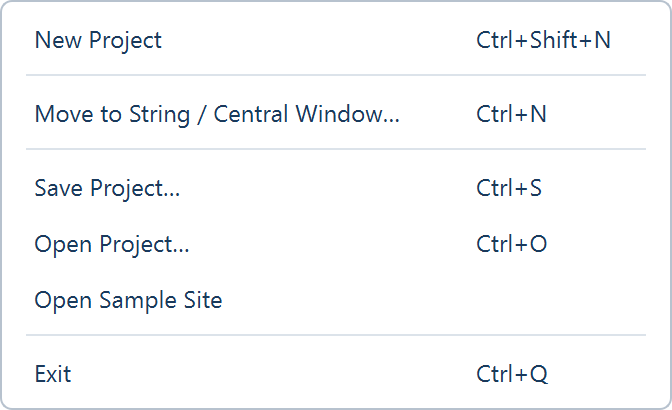
| Item | What it does |
|---|---|
| New Project (Ctrl+Shift+N) | Opens a fresh window at the defaults, in the same design as this one |
| Move to String / Central Window… (Ctrl+N) | Opens the New design window and launches a second window for the design you choose; this one stays open |
| Save Project… (Ctrl+S) | Writes the current session to a .slp file |
| Open Project… (Ctrl+O) | Reads a .slp file back |
| Open Sample Site | Loads the bundled sample site — one boundary with a pond, a transmission line and an obstruction |
| Exit (Ctrl+Q) | Closes the application |
Saving a project
Use Save project, beside Export ▾ at the right of the view tabs in every view, or File ▸ Save Project…. Choose a folder and a name; the file type row reads PV Layout Project (*.slp), and the status bar confirms with "Project saved (full): …". If the file cannot be written, a Save Failed box opens with "Could not save project file:" and the reason.
Saving is allowed at any time, including while the layout is out of date. The state is saved with it: a project saved out of date opens out of date.
Save after anything you would not want to redo — a run whose inputs took a while to settle, a set of hand edits, a diagram you have laid out, or a materials list you have corrected.
Reopening a project
File ▸ Open Project…, then pick the .slp file. The session is restored
and you carry on from where you stopped. Any open ICR block summary windows
close first. A project saved in a different design asks first, under the title
Design Mode Mismatch; a project whose inputs could not all be restored
opens with Partial Restore — "Input settings restored with warnings:".
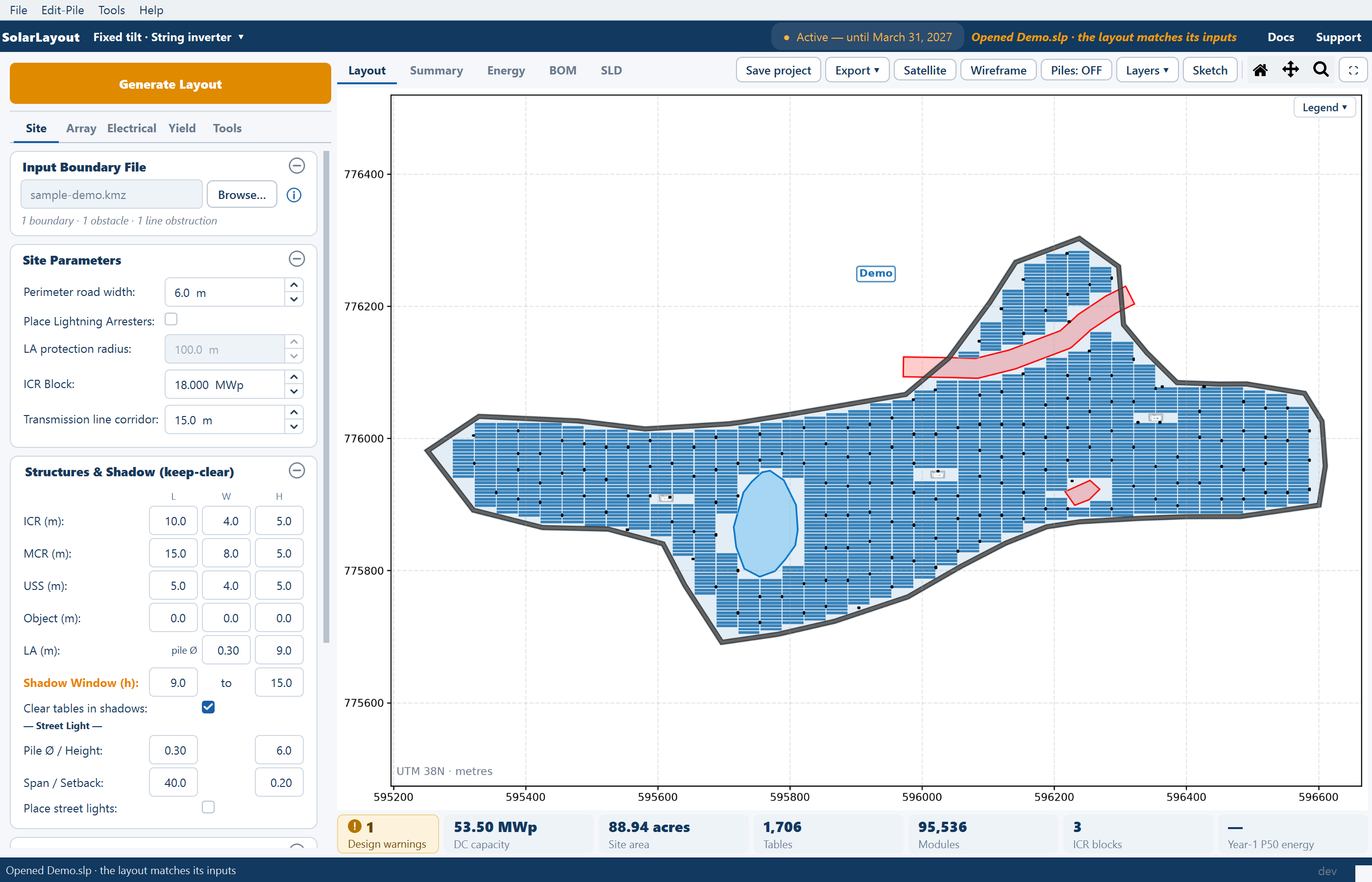
The status bar says what state the project opened in:
| Case | Status bar |
|---|---|
| A layout that matches its inputs | "Opened <name> · the layout matches its inputs" |
| A layout that is out of date — it was saved that way, or an input file is missing or has changed | The out-of-date line, "Out of date: … Regenerate the layout to update results and exports." |
| A project saved by an earlier release of the application | "Opened <name>, saved by an earlier version: 1 input was restored from its saved layout" (or "… N inputs were restored …") |
| A project with no layout | "Project loaded: <name>" |
Exports and layout tools without a Generate
A project whose layout matches its inputs opens with these ready, without generating again:
- Export ▾ offers its exports: the Google Earth file (unless the site was loaded as layout only), the CAD drawing, the ICR-block drawing set and PDF, the cable schedule, the Word report and the image.
- Satellite, Piles and the ICR blocks layer are available (and off); saved piles can be shown.
- The arrester layer is available, and so are the three cable layers when the saved run had cables calculated.
- On the Tools tab, Draw Rectangle and Draw Polygon work (with Undo Last and Clear All when there are obstructions), and so do Place MCR and Place Object.
- Calculate Energy is available where the site's location is known.
- The Electrical tab shows the saved grouping of inverters into ACCBs and transformers.
A project that opens out of date
A project opens out of date when it was saved that way, or when an input it was generated from is no longer as it was. For each missing module, inverter, weather or contour file, the list of changes reads "not found at <path>" and the file's row on its card reads "Not found: <name>". The layout is still shown, greyed, but every export is refused until the layout is current again. The path is kept in the project the next time you save.
Opening a project restores exactly the files that project was saved with, never those of another open window. See Out-of-date results.
Starting fresh
File ▸ New Project opens a fresh window at the defaults in the same design; the current window stays open, so save it first if it is worth keeping — nothing is written to disk unless you write it.
Moving to a different design
The mounting and inverter choices belong to the window and cannot be changed inside it. The design chip in the ribbon — reading Fixed tilt · String inverter ▾ or the like — and File ▸ Move to String / Central Window… both open the New design window and launch a second, independent window beside this one. The new window starts empty: it does not inherit the boundary file, the inputs or the layout. See Choosing a design mode.
The file checks itself when it opens
A project file is a single binary container, not a text file. It carries a checksum computed over its own compressed contents, which is verified before anything is loaded. A file that has been altered, truncated by a failed copy, or is not a project file at all fails that check and is reported as an error — Open Failed, "Could not open project file:" — instead of opening.
Do not edit a .slp file by hand, and do not try to produce one from another
tool or a script. Any change to its bytes — including a well-intentioned one —
makes the checksum disagree with the contents, and the application refuses the
file rather than loading part of it.
Two practical consequences:
- Copy project files whole. Move them with a normal file copy, and check the copy opens before deleting the original. A transfer that stops partway leaves a file that does not load.
- To get the design out of the application, export it. Export ▾ carries the layout into formats other tools read: a Google Earth file, a layered CAD drawing, an ICR-block drawing set and PDF, an Excel cable schedule, the Word project report, and the plot as an image. The CAD drawing is in UTM metres, or in the drawing's own coordinates for a CAD or image boundary placed by hand or loaded as layout only. See The project report.
Comparing several designs on one site
Every window is its own session, and two or more can be open at once, so options can be compared side by side as well as as separate project files. A workable habit:
- Load the boundary file, set the inputs your design fixes, generate, and save as one project per option — a portrait table against a landscape one, a derived row pitch against a tighter one you override, arresters on against off. File ▸ New Project gives each option its own window.
- Give each file a name that states the variable, not a version number, so the comparison survives being read months later.
- Read the same Summary rows in each — DC capacity (MWp), Full tables, ICR blocks and, once energy has been calculated, CUF (%) and the probability rows. Copy on the Summary view puts each sheet on the clipboard for a spreadsheet.
Changing the mounting or the inverter topology is the one comparison that needs the design chip rather than New Project, because those belong to the window rather than the inputs.
Where to go next
Out-of-date results
How a reopened project knows whether its layout still matches its inputs
The project report
The Export menu: the Word report, the Google Earth file and the CAD drawings
Choosing a design mode
Why a design change means a second window
Troubleshooting
What to do when a file does not open or a run does not finish
CAD drawing export
The layered drawing export — every layer and what it carries, which coordinates it is written in, which layers are conditional, and the ICR-block drawing set beside it.
Every parameter and its default
The complete input reference — every card on the five stage tabs and every study window, each field's shipped default, its range, and what it changes.