Inverter control rooms
What an inverter control room is, how many the plant gets, where they are placed, the tables they clear, and how to move one by hand.
An inverter control room (ICR) is the building where the plant's collection cables terminate and its medium-voltage export begins. In a string-inverter plant the inverters stand out in the field and run their AC cables into it. In a central-inverter plant the central inverters themselves stand inside it.
The application places the rooms for you. It works out how many the plant needs from the capacity block you set, divides the tables into that many groups, places a room at the centre of each and clears the tables it stands on. You can then move any room by hand if the ground does not suit it. The tables finally wired to each room form its ICR block.
The footprint
A control room is drawn and cleared as a rectangle with a height, and all three dimensions are yours to set on the Structures & Shadow (keep-clear) card of the Site tab.
| Dimension | Default | What it is |
|---|---|---|
| Length | 10.0 m | The building's east–west extent |
| Width | 4.0 m | The building's north–south extent |
| Height | 5.0 m | Drives the shadow the building casts |
Length is always the east–west side and width the north–south side, for the control room and for every other structure on that card. Enter the building you are actually going to build: the length and width are what the placement has to find room for and what clears tables, and the height is what casts the shadow. See Structures and shadow.
How many the plant gets
The count comes from one field. ICR Block on Site parameters is the DC capacity one control room serves, and defaults to 18.000 MWp with a range of 0.1 to 500.
The count is worked out for each separate piece of land, not for the plant as a whole:
- The tables are split into separate pieces of land. Two tables are on the same piece when a chain of tables links them with no gap in the chain wider than 300 m. Internal roads, corridors and setbacks are far narrower than that, so they never split a piece; a plant split by a wide water body or an excluded valley can be several pieces.
- Each piece gets its own rooms: the piece's capacity divided by the ICR Block, rounded up. A half table counts as half a table's capacity here.
- The plant's count is the sum over its pieces.
On a site in one piece that is simply the plant's capacity divided by the block size, rounded up. On a site in several distant pieces it can be more, because each small far-off piece gets a room of its own rather than being cabled hundreds of metres to a neighbour's.
Rounding up means a plant — or a piece of land — that overshoots a block boundary by a small margin gets a whole extra room. The capacity is then shared equally between the rooms of that piece, so every block becomes a little smaller; there is no small left-over block. It is worth checking the count against your own single-line concept before you accept it.
You cannot set the count directly. It follows the capacity that is actually placed — so the road width, obstructions and the building-shadow keep-clear can all change it — and how the land splits into pieces.
Set the block size to the capacity your transformer and switchgear design actually serves. It is the single most consequential number on this page: it sets how many buildings the plant carries, how the tables are grouped around them, how far the AC runs are, and how many medium-voltage circuits leave the plant.
Where they go
The rooms are placed after the table grid, once the plant's capacity is known, and their positions come from where the tables actually are rather than from a geometric division of the site.
The tables of each piece of land are divided into exactly as many compact groups as the piece has rooms, balanced so that each group carries close to the same capacity — within about 5 % of the average. A group never reaches across two pieces of land. Each room is then placed at the centre of its group, so the room sits near the middle of the load it serves, which is what keeps the AC runs from that group short. If the centre itself is not free, the nearest free position is used, searched north and south first and then outward.
Each room must fit entirely inside the usable area, at the length and width you set, the same rule the tables follow. A position that would put part of the building in the perimeter road band, in a water body, in a transmission line corridor or on excluded ground is not used. See How placement works.
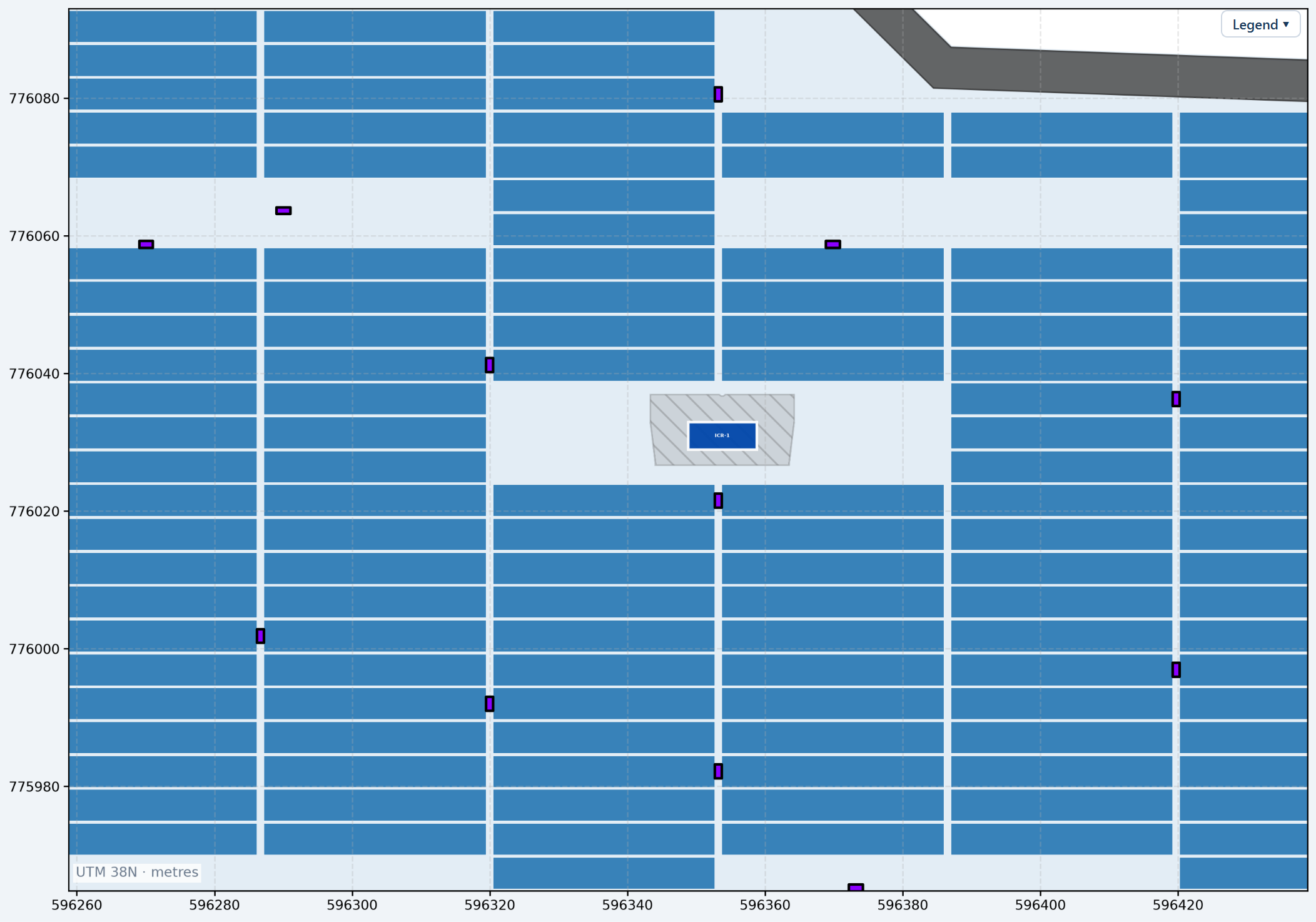
A room that finds no place
A room that finds no valid position anywhere near its group is not dropped silently. It is still counted as needed, and the plot is reported with the design warning ICR not placed, for example "2 of the 6 ICRs this plot needs found no room in it." The warning appears in the Summary view, on the Design warnings chip and in the PDF summary and the BOM — see Design warnings. The usual causes are a building too large for the gaps the site leaves, or a piece of land too narrow to take one; check the length and width fields first.
Seeing the blocks
Which tables belong to which room is a layer of its own. Open Layers ▾ in the Layout view's tools and switch ICR blocks on: each block — the tables wired, through their inverter or string monitoring box, to one room — is filled in its own colour and outlined. The row is off by default and becomes available once the inverters are placed.
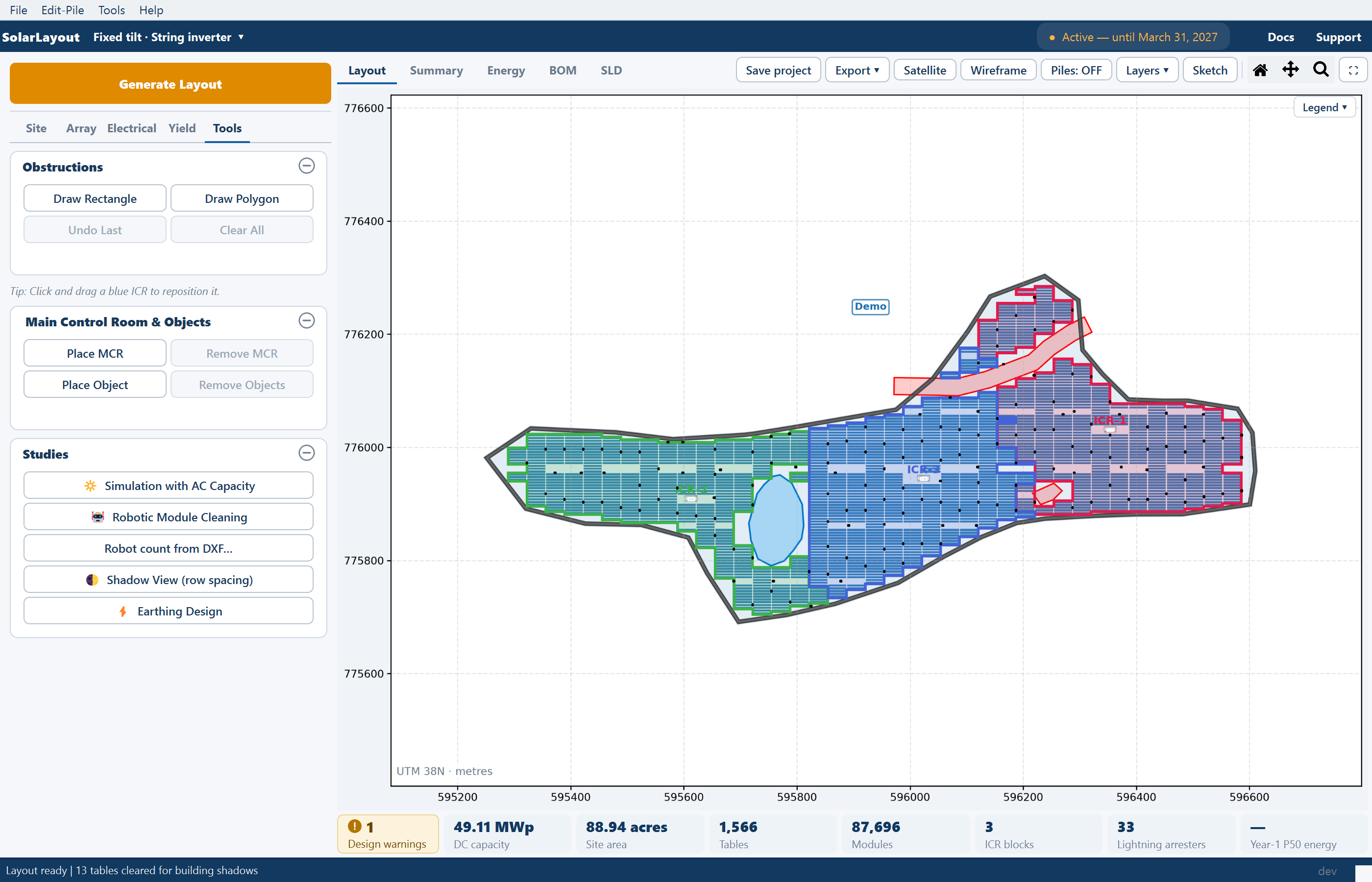
With the layer on, clicking a block opens a window summarising it — its capacity, tables, inverters, transformer, cable lengths and piles. The blocks, that window and the ICR-block exports are covered in ICR blocks.
The tables a room clears
Any table overlapping a control room's footprint is removed. The building wins; the ground under it and the ground its footprint touches carry no structures.
Removing tables changes the capacity the count was worked out from, so the count is checked again:
- After the footprints are cleared, the count is worked out afresh from the tables that remain. If it differs, the rooms are placed again with the new count. This check can raise the count or lower it.
- After the building-shadow keep-clear, on a fixed-tilt plant, the count is worked out once more. If fewer rooms would now do, the lower count is tried, and kept only when the settled layout still needs no more. This check only ever lowers the count.
This is why the room count and the table count in the Summary view are consistent with each other rather than with a figure you would get by dividing the site area by the block size.
Moving a control room by hand
The automatic position is derived from the tables. It knows nothing about where the site road reaches, where the ground is firm enough for a building, where the existing site access is, or where the owner will allow a structure. When one of those decides the position, move the room. The Tools tab carries the reminder "Tip: Click and drag a blue ICR to reposition it."
Leave Pan and Zoom inactive
Dragging a room only works when neither Pan nor Zoom in the Layout view's tools is holding the mouse. If one of them is active, click it off first — otherwise the drag moves the view instead of picking up the building.
Click and hold the room
Click the dark blue rectangle and keep the button down. Fit the view first with Home, then roll the mouse wheel over the room you want, so you are picking up a building and not a table beside it.
Drag it inside the perimeter road and release
Drop it anywhere the whole footprint stays inside the plant — inside the perimeter road, clear of the exclusions. On release the layout rebuilds around the new position.
Check what came back
An invalid drop snaps back to where the room started, so a room that returns to its original position was dropped somewhere it cannot stand. A valid drop rebuilds the layout, so the tables the room used to clear come back and the tables at the new position go away. The number of rooms does not change.
A drag is ignored while cables are being routed. After an edit on the plot the status bar reads "Cables are being routed… Obstruction, MCR and object tools and ICR dragging are back when they finish."; wait for the run to end, then drag.
Moving a room away from the centre of its group of tables lengthens every AC run from that group. If cable lengths matter to your estimate, re-check the cable rows of the Summary view after the move rather than assuming they are unchanged.
In a central-inverter design
The building's role changes with the electrical topology, and so does what it contains.
String inverters stand out in the field, in the gap bands between rows. DC string cables run from the tables to the inverters, and each inverter's AC cable runs to a control room, where the medium-voltage circuit that leaves the plant begins. An inverter starts on the room nearest to it along the plant, up to the number of inverters that room's block is rated for; a room that is over-full hands inverters on to a neighbouring room. A room still over its rating is reported as the design warning ICR over rating.
Either way, the medium-voltage cables leave the control rooms and run to the main control room, sharing a trunk where their routes converge rather than running parallel lines. See Cable routing.
On a site with several plant boundaries, each plant's rooms route their medium-voltage cables to a unit substation in their own plot instead. See Multi-plot sites.
The shadow a control room casts
A 5 m building next to a row of modules shades it. The application computes the year-round shadow footprint of every control room, main control room and placed object over the Shadow Window — the band of solar hours you care about, 9.0 to 15.0 by default — and, with Clear tables in shadows on, removes the tables that fall inside it.
That option is on by default, so a first run already keeps tables out of building shadows. Switching it off leaves shaded tables in place, which raises reported capacity and makes the yield estimate optimistic for those rows. Change the room's height and the shadow footprint changes with it.
The fields that decide a control room
Four fields, on two cards of the Site tab, decide the rooms directly:
| Field | Card | What it decides |
|---|---|---|
| ICR Block | Site Parameters | How many rooms each piece of land carries, and therefore how its tables are grouped around them |
| ICR length, width and height | Structures & Shadow | The footprint that has to fit and that clears tables, and the height that casts the shadow |
| Clear tables in shadows | Structures & Shadow | Whether the tables inside a room's year-round shadow are removed |
| Shadow Window | Structures & Shadow | The band of solar hours the shadow footprint is accumulated over |
Everything that changes the placed capacity changes the count as well: the perimeter road width, the corridors, the obstructions and excluded terrain all take ground, and so tables and capacity, away. And anything that leaves parts of the plant more than 300 m apart — a large water body, an obstruction across a narrow neck of land — makes separate pieces, each with rooms of its own.
Checking the rooms after a run
Four things are worth a look before you accept a layout:
- The count against your electrical concept. The ICR blocks chip under the view is the number of rooms placed. If it is more than your single-line concept expects, either the plant has overshot a block boundary or the site has split into separate pieces of land — adjust the block size, or accept the extra building. If a design warning says a room found no place, the plant is a room short.
- Where each room landed. Zoom into each one with the mouse wheel. A room at the centre of its group of tables is what you want; a room pushed to one side of its group is usually a room that had nowhere else to fit, and it is the first candidate for a hand move. The ICR blocks layer shows the groups.
- Whether the ground is buildable. The application knows the boundary, the exclusions and the slope limits. It does not know where the site access road will run, or where the ground is firm. Those are yours to check.
- The gap the room left. Turn on Wireframe and look at the cleared footprint. If it is much larger than the building you intend, the length and width fields are set to something you did not mean.
What the outputs report
The ICR blocks row of the Summary view carries the count of rooms placed in each plant, with a Total column on a multi-plot site; the ICR blocks chip under every view carries the same figure for the site. In a string-inverter design the AC cable to ICR (m) row is the total length of the runs from the inverters into the rooms; in a central-inverter design it is replaced by DC cable to central inverter (m). Every row is listed in Summary rows.
For each room on its own, click its block with the ICR blocks layer on. The exports under Export ▾ in the view header go further than the Summary view and break the plant down per control room:
- Export ICR-Block PDF — one A3 PDF with the whole plant and a table of the blocks on the first sheet, then one sheet per block with its key plan and details.
- Export ICR-Block DXF — one drawing set with the whole plant on the first sheet and then one sheet per block, each with its summary table. Both block exports are described in ICR blocks.
- Export Cable Schedule (Excel) — a workbook with one sheet per ICR block: the DC strings from each table row to its inverter or monitoring box, the AC or DC-trunk feeders, and the collection runs to the transformers and the main control room. It does not need cables calculated, but without them the lengths are straight-line distances × 1.15. See CAD export.
- Export Detailed Project Report — the Word document, whose design summary carries the inverter and cable figures by control room. See The project report.
Where to go next
ICR blocks
The tables wired to each room, its summary window and the block exports
Site parameters
The capacity block that sets how many rooms the plant gets
Structures and shadow
Footprints, heights, the shadow window and the clearing rule
Design modes
What changes between string- and central-inverter plants
Maximizing placement and half tables
Two options that fit more capacity onto an awkward boundary, what each costs in regularity, and when a regular plant is worth more than the extra tables.
ICR blocks
What an ICR block is, how to see the blocks on the plot, the summary window each block opens, and the ICR-Block PDF and DXF exports.