ICR blocks
What an ICR block is, how to see the blocks on the plot, the summary window each block opens, and the ICR-Block PDF and DXF exports.
An ICR block is one inverter control room (ICR) and the tables wired to it. A table belongs to the block of the control room that its string inverter — or its string monitoring box (SMB), in a central-inverter design — feeds. The block is therefore an electrical grouping, and it is the unit a block transformer, a cable schedule sheet and a construction package are usually organised around.
Every output that talks about blocks uses that definition: the ICR blocks layer, the block summary window, and the two block exports. The blocks are known once the inverters are placed, which happens on every Generate Layout; before that a block has no tables.
Blocks and the placement groups
The control rooms are placed first, each at the centre of a group of tables of near-equal capacity. See Inverter control rooms. The inverters or SMBs are then assigned to the rooms, each starting on the room nearest to it along the plant and moving to a neighbouring room only when that room is full. So a block — the tables wired to a room — is close to the group the room was placed for, but not identical to it: along the edge between two groups a few tables can end up wired to the neighbouring room. How devices are assigned is on Cable routing.
Seeing the blocks
Open Layers ▾ in the Layout view's tools and switch ICR blocks on. Each block is filled in its own colour and outlined, and labelled with its name. The row is off by default and greyed out until the inverters are placed; it stays available while the layout is out of date.
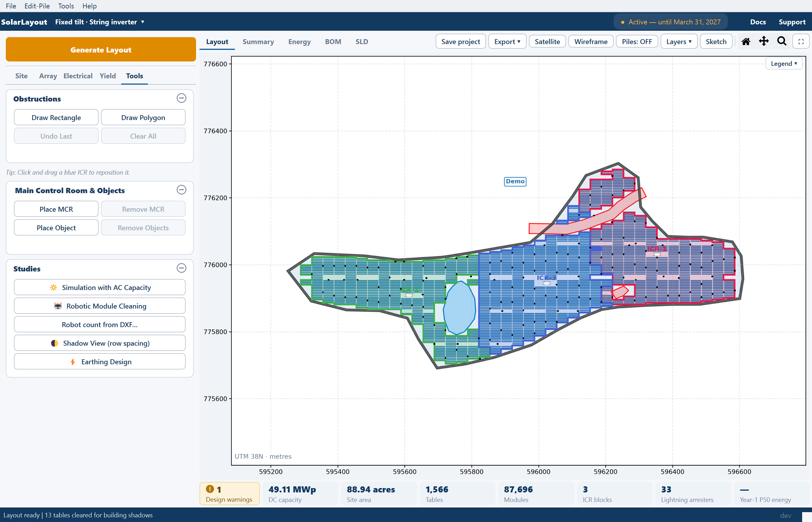
- Names. Blocks are named ICR-1, ICR-2 and so on, after the number of their control room in the plant.
- Outlines. A block's outline hugs its tables, closes the gaps inside the block, keeps off the other blocks and is clipped to the plant boundary. A block split by an obstruction or a water body can therefore have several pieces.
- Colours. The colours cycle through a fixed set of sixteen.
The layer is the quickest way to see how the plant is wired: which tables feed which building, and whether a block reaches across a corridor or a pond to pick up tables the neighbouring room would serve more directly.
Opening a block's summary
With the ICR blocks layer on, every block opens a summary window of its own. There are two ways in.
By clicking. Click a block — press and release the left mouse button on the same block without moving it. A double-click, a drag, or a press on the control room building itself does not open anything: a press on the building starts dragging the room. Hovering over a block names it in the status bar, "ICR-3 — click to open its summary"; nothing is drawn on the plot.
From the keyboard. Switching the layer on gives the plot the keyboard.
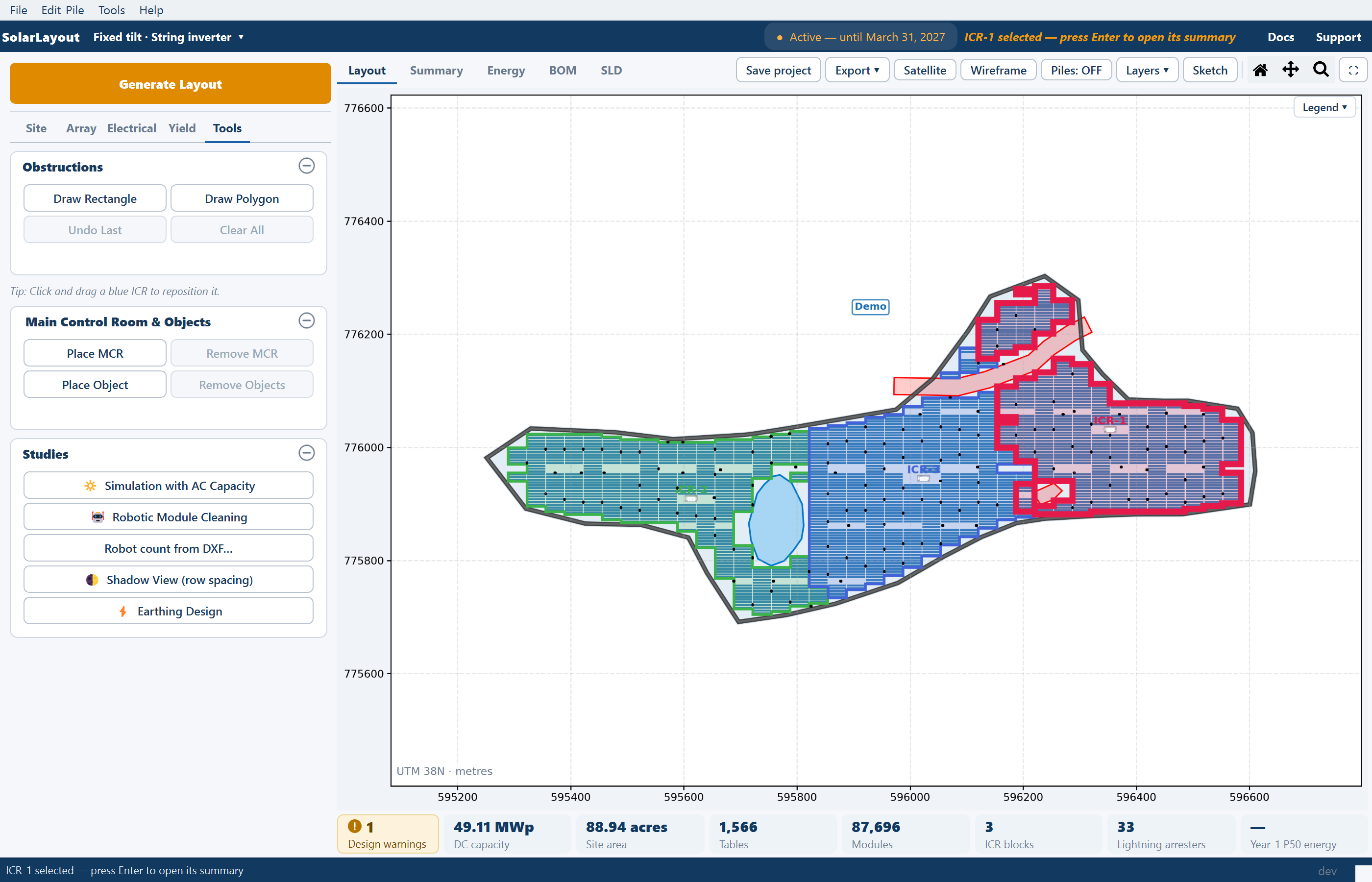
Select a block with the arrow keys
→ or ↓ selects the next block, ← or ↑ the previous one. The selected block gets a thick outline, and the status bar reads "ICR-3 selected — press Enter to open its summary".
Press Enter
The selected block's summary window opens.
Nothing opens while Sketch Mode, the SLD view or the BOM view is on, while Pan or Zoom is active, or while you are placing a main control room, an object or an AC start point, or drawing an obstruction. Finish or cancel that first.
Each click or Enter opens another window, so you can open several blocks side by side and compare them. The windows do not block the main window; they open at its top right, each one offset from the last.
The summary window
The window's title names the block and the plant, for example "ICR-3 — Demo". A strip across the top repeats the name beside a swatch of the block's colour, with two chips for the design: Fixed tilt or Single-axis tracker, and String inverter or Central inverter.
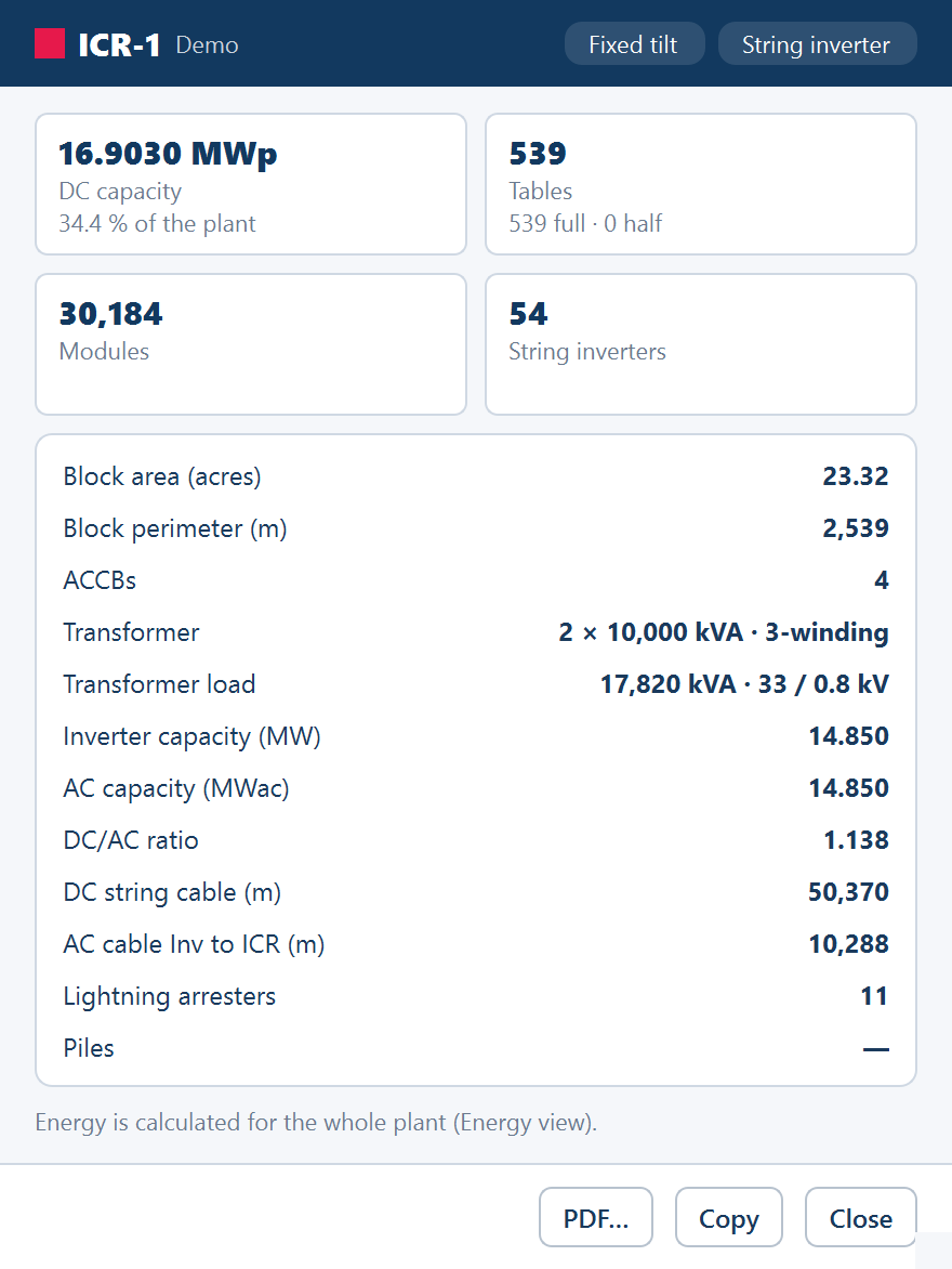
Four tiles give the block's size at a glance:
| Tile | Value | Note under it |
|---|---|---|
| DC capacity | The block's DC capacity, in MWp to four decimals | The block's share of the plant, as a percentage |
| Tables (Trackers in a tracker design) | The number of tables in the block | How many are full and how many half, "n full · m half" |
| Modules | The modules on the block's tables | — |
| String inverters (SMBs in a central-inverter design) | The devices wired to this room | In a central-inverter design, the number of central inverters |
Under the tiles a card lists the rest, in this order. A — means the figure is
not available for this design or this run.
| Row | What it is |
|---|---|
| Block area (acres) | The area inside the block's outline |
| Block perimeter (m) | The length of the block's outline |
| ACCBs | The AC combiner boxes in the block — string-inverter design only. See ACCB and transformers |
| Transformer | The block's transformers, for example "1 × 16,000 kVA · 4-winding"; without an inverter file the rating reads "rating needs OND" |
| Transformer load | The load on them and the voltages, for example "13,200 kVA · 33 / 0.8 kV"; — without an inverter file |
| Inverter capacity (MW) | The plant's inverter capacity, shared out by this block's share of the inverters; — without an inverter file |
| AC capacity (MWac) | The plant's AC capacity shared out the same way — the capacity from the AC-capacity study when one was run, otherwise the inverter capacity |
| DC/AC ratio | The block's DC capacity divided by its inverter capacity |
| DC string cable (m) | The DC string cable routed within the block |
| AC cable Inv to ICR (m) — DC trunk SMB to CInv (m) in a central-inverter design | The inverter feeders, or the DC trunks, into this room |
| Lightning arresters | The arresters in the block. Each one counts in the block whose outline holds it, or the nearest block, so the blocks add up to the plant total |
| Piles | Each table's own piles, added up for the block, once a pile pattern exists. See Pile layout |
The two cable rows need Calculate cables on for the run; the inverter and AC capacity rows and the ratio need an inverter (OND) file. A note under the card says which of those is missing — "Cable lengths need Cable Calc.", "Inverter capacity needs an OND file." — and always ends "Energy is calculated for the whole plant (Energy view)."
Energy is not split per block
The block window carries no energy figures, deliberately. Yield is calculated for the whole plant, in the Energy view. If you need a block's share, the DC capacity tile's percentage of the plant is the figure to scale by.
PDF…, Copy and Close
| Button | What it does |
|---|---|
| PDF… | Saves this block's sheet as a one-page PDF — the block, a key plan of the plant and the table above. The save dialog is titled "Save ICR-3 PDF". The sheet is the same as the block's own sheet in the ICR-Block PDF, below |
| Copy | Copies the summary as a two-column table — the block, the plant and every row, tiles included — which pastes into Excel as two columns. The button reads Copied for a moment |
| Close | Closes the window |
PDF… needs active access, like the exports on the Export ▾ menu.
While the results are out of date
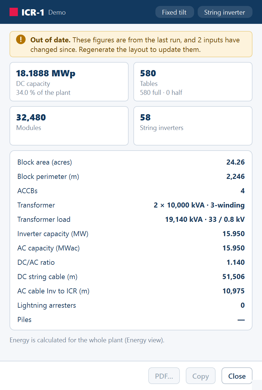
When an input changes after a run, the layout is out of date until you regenerate or change the value back — see Out-of-date results. The block windows follow it. A banner across the window reads Out of date. These figures are from the last run, and 1 input has changed since. Regenerate the layout to update them., and PDF… and Copy are disabled, with the tooltip "Inputs changed since the last run. Regenerate first." A window opened while the layout is out of date starts with the banner.
The windows close themselves when the blocks they describe change under them:
- when the inverters are placed again — after dragging a control room, drawing an obstruction or any other edit on the plot that moves them;
- when the plant is regrouped — after loading an inverter file, or changing the ACCB & Transformer card (Transformer in a central-inverter design) on the Electrical tab;
- when you open a project.
The block exports
Two items on the Export ▾ menu, in the view header, produce the whole set of blocks at once:
| Item | What it produces |
|---|---|
| Export ICR-Block PDF | One A3 PDF: a plant sheet showing every block, then one sheet per block |
| Export ICR-Block DXF | One CAD drawing set: a plant sheet with a table of the blocks, then one sheet per block with its summary table |
Both are available once the inverters are placed and the layout is current,
and both need active access. On a site where more than one plot has control
rooms, the block names in both exports carry the plot's number, P1-ICR-1,
P2-ICR-1 and so on, so that blocks from different plots stay apart. See
Multi-plot sites.
Export ICR-Block PDF
The save dialog is titled "Save ICR-Block PDF". Every sheet is A3 landscape, in the same engineering frame and title block as the project report, and the status bar reports "ICR-block PDF exported (n pages): …". There is one sheet for the plant and one for each block; a layout with no control rooms gets the plant sheet alone.
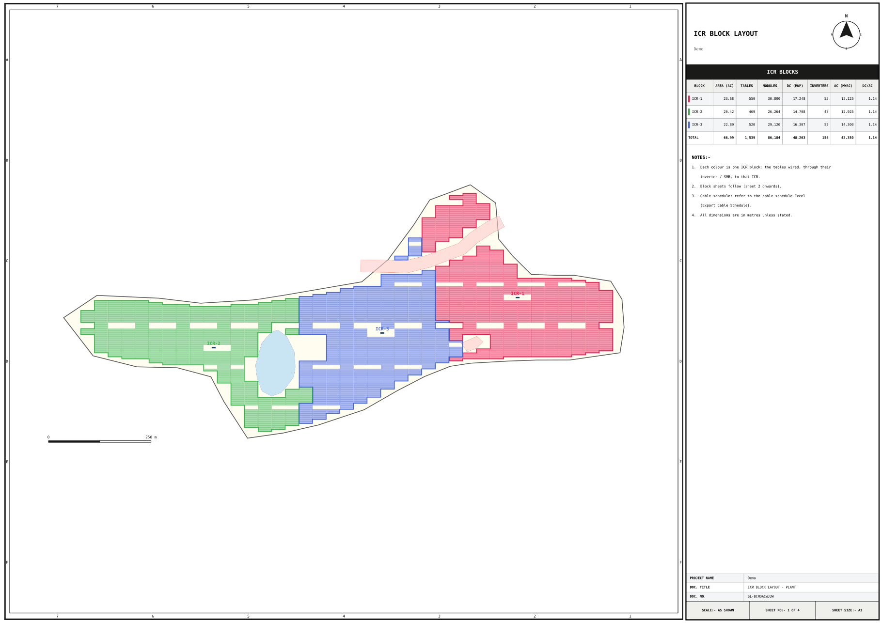
Sheet 1, the plant. The whole plant, with each block's tables in a lighter shade of its colour, its outline and its labelled control room, plus a scale bar and a north arrow. Beside it, a table headed ICR BLOCKS gives one row per block — BLOCK · AREA (AC) · TABLES/TRACKERS · MODULES · DC (MWP) · INVERTERS/SMBS · AC (MWAC) · DC/AC — with a TOTAL row when there are several blocks. The notes explain the colouring: "Each colour is one ICR block: the tables wired, through their inverter / SMB, to that ICR." The drawing is titled ICR BLOCK LAYOUT - PLANT.
Sheets 2 onwards, one per block. The drawing zooms to the block: its tables in its colour, the other blocks in grey, and its inverters or SMBs drawn dark. A KEY PLAN shows the whole plant with this block in red. A BLOCK DETAILS table lists every row of the summary window, and the notes name the block's sheet in the cable schedule and state that area and perimeter are measured on the block outline. Each sheet is titled ICR BLOCK LAYOUT - ICR-n.
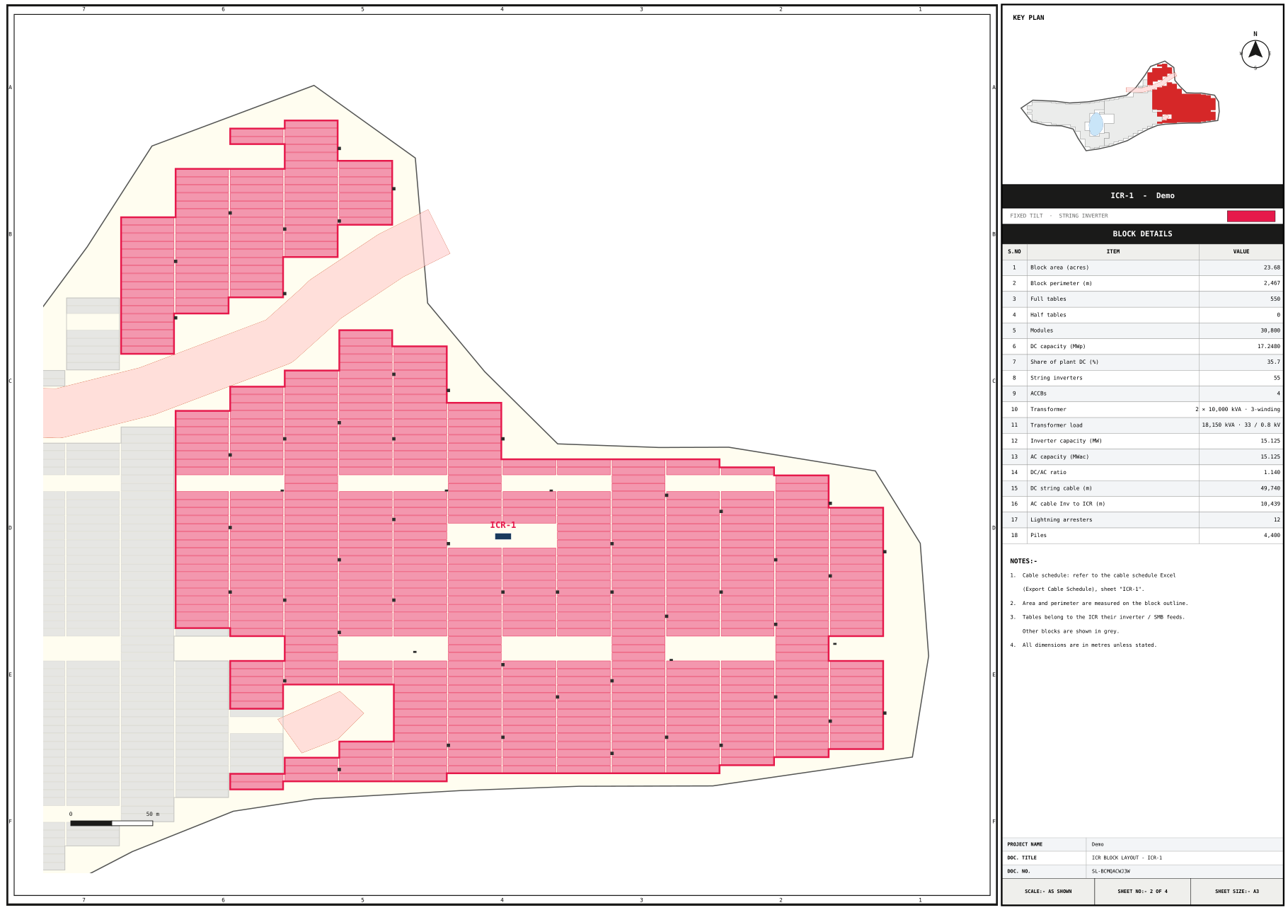
The Piles row is filled whenever a pile pattern exists, whether or not the pile overlay is on.
Export ICR-Block DXF
The save dialog is titled "Save ICR-Block DXF", and the status bar reports "ICR-block DXF exported (n block sheets + plant): …" — or "DXF exported (no ICR blocks — whole plant only): …" when there are no blocks.
The model space is the complete Export DXF drawing, every layer included; see CAD export. The sheets are A3 landscape layouts in paper space:
| Sheet | What it holds |
|---|---|
| 01 - Plant | A viewport on the whole plant, and beside it the title ICR BLOCKS - and the plant names, the same blocks table as the PDF, and notes pointing to the block sheets and the cable schedule |
| 02 - ICR-1, 03 - ICR-2, … | A viewport on the block, and beside it the title ICR-n SUMMARY - and the plant name, the design (for example Fixed tilt - String inverter), an ITEM / VALUE table of the summary window's rows, and the block notes |
The drawing adds its own layers:
| Layer | What it carries |
|---|---|
SUMMARY_TABLE | The tables and notes on the sheets, as paper-space text |
ICR1_TABLES, ICR2_TABLES, … | Each block's tables, in the block colour |
ICR1_BND, ICR2_BND, … | Each block's outline and label, in the block colour |
Each block sheet freezes the other blocks' layers, so its viewport shows its
own block. The sheet text uses plain characters a CAD font can show: a
transformer prints as 1 x 16,000 kVA, 4-winding.
Two things follow what is on screen when you export:
- Piles — the Piles row, and the
PILESlayer, appear only when a pile pattern exists and the pile overlay is on (Piles: ON). Switch the overlay on before exporting if the set is to carry piles. - Arresters — the arrester layer follows the Lightning arresters row in Layers ▾.
For the cable lengths behind each block, export the cable schedule, which has one sheet per block. See CAD export.
Where to go next
Inverter control rooms
What an inverter control room is, how many the plant gets, where they are placed, the tables they clear, and how to move one by hand.
Lightning arresters
How arresters are placed on a coverage grid, what each one clears from the layout, the settings that control the radius and the footprint, and where they show up.