Pile layout
Define the pile pattern of a full table, and of a half table — derived or your own — in the Pile layout window, then count, draw and export every pile.
The pile layout feature produces a construction document: the position of every foundation pile in the plant, drawn and tabulated, in a form a setting-out team can work from. You define the pattern once, on a full table — a full tracker in a tracker design — and the application places it on every full table in the plant. Half tables carry a pattern of their own, which the application derives from the full one unless you draw it yourself.
It is a construction output, not a design check. Nothing here validates the pile pattern against a structural design — the number of piles, where they sit along the table and how big they are all come from you, or from the structure supplier's drawing.
Two patterns: full and half
A plant repeats one table design across the site, so the pattern only has to be described once. There are two:
| Pattern | Goes on | Where it comes from |
|---|---|---|
| Full pattern | Every full table or tracker | The piles you place |
| Half pattern | Every half table or half tracker | Derived from the full pattern, or your own, drawn on the half unit |
With no full pattern there are no piles anywhere, on full or half units. A plant without half units only ever needs the full pattern, and the window then shows no trace of the second one.
A half unit is halved along its long axis: a fixed-tilt half table is half the width of a full table (east–west), and a half tracker is half the length of a full tracker (north–south). See Maximizing placement and half tables.
The coordinate frame
A pattern is drawn in the unit's own local frame, independent of the site — the window's strip states it: origin at the bottom-left corner · X east, Y north.
- The origin, (0, 0), is the unit's bottom-left corner — its south-west corner on the ground. A half unit is measured from its own south-west corner.
- X runs east, across the unit's width.
- Y runs north, up the unit's height.
Both axes are in metres, and the extent is the unit's own dimensions, set by the module size, the module counts and the gaps in MMS-Table Configuration (or Tracker Configuration). See Table configuration. A coordinate outside the range 0 to the width, or 0 to the height, puts that pile off the unit.
The frame is only as big as the table
The extent of the frame is the table itself, so it changes whenever the table changes. Modules per row and the east–west gaps set how far X can run; rows per table and the north–south gaps set how far Y can run. Orientation changes both: a portrait table puts each module's short side east–west and its long side north–south, and a landscape table reverses that.
The consequence is practical. A pattern entered against a portrait table does not transfer to a landscape one, and a pattern entered before you changed the modules per row no longer sits where you meant it to. If you change the table configuration, open the window again and check the pattern against the new frame before exporting.
What a pile is
Each pile is drawn as a circle of the Pile radius, centred on the (X, Y) you entered. One radius applies to both patterns; it defaults to 0.15 m and can be set from 0.01 to 2 m.
The radius is a drawing and setting-out figure — the pile as it appears in plan. The pile diameters for lightning arresters and street lights are separate fields on the Structures & Shadow card and are not part of this pattern. See Structures and shadow.
How a pattern reaches the ground
Each unit keeps its own position, and its pattern is applied relative to that unit's own south-west corner. So a pile's position on the ground is:
the unit's south-west corner, X metres east and Y metres north.
That relation lets you check the export by hand. Take any table, take its south-west corner, step east by the pattern's X and north by its Y, and that is the coordinate the export gives for that pile. The coordinates are in metres: UTM for a Google Earth boundary or a CAD drawing located by its own coordinates, and the drawing's own coordinates for a CAD or image boundary placed by hand or laid out without a location.
Opening the Pile layout window
Two routes open the same window. Piles: OFF in the Layout view's tools is disabled until a layout exists; Edit-Pile ▸ Define Pile Layout… on the menu bar is the route to come back to the pattern later. On a narrow window the Piles button folds into the Layers ▾ popover as a row of its own — it has moved, not gone.

Generate a layout first
There is nothing to apply a pattern to before that, so Piles: OFF stays greyed out until a layout is on screen.
Click Piles: OFF
The first time you use it, the Pile layout window opens so you can define the pattern. Its strip names the unit — One table (One tracker) on a plant without half units, Full table or Half table on a plant with them — and gives its size, w × h m; a chip counts the piles placed so far.
Place the piles on the unit
The right-hand side draws the unit to scale, with a red square at the origin: click inside the outline to place a pile. On the left, + Add adds a pile at the centre of the unit for you to move by editing its X and Y, Remove deletes the selected piles, Clear removes every pile, and the list — #, X (m), Y (m), to three decimals — is the same pattern as numbers, which you can edit directly. Set the Pile radius once for the whole design.
Or let Auto grid… place an even pattern
Auto grid… asks for Piles per row (along X, east; 4 by default) and Rows of piles (along Y, north; 2 by default), places them evenly spaced, inset 6% from the ends and 10% from the sides, and replaces the piles placed so far. Its button reads Place n piles. It works on the unit you are editing, so on the Half tab the grid fits the half unit, and it remembers the counts you last used.
Apply to all tables
The footer shows the plant's total, "N piles across the plant", and the primary button reads Apply to all N tables (trackers in a tracker design). It is disabled, with the reason "Place at least one pile", until the pattern has a pile in it. Applying switches the overlay on, the tools button reads Piles: ON, and the status line reports the result.
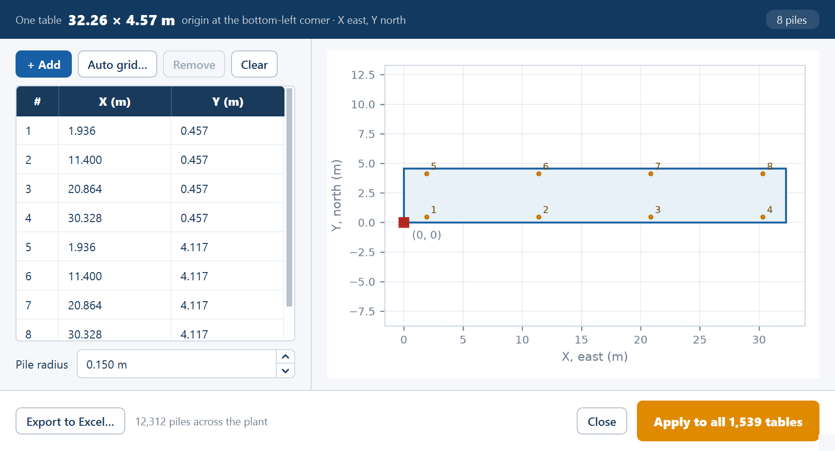
The status line after applying reads, on a tracker design with tracker for table:
| Plant | Status line |
|---|---|
| No half units | "Piles applied: n per table · N piles." |
| With half units | "Piles applied: n per full table, m per half table · N piles." |
| Pattern emptied | "Piles removed from all N tables." — the button reads Remove piles from all N tables |
Export to Excel… in the footer writes the coordinates to a workbook — see below — and Close leaves without applying anything.
Half tables: the Full / Half switch
On a plant with half units the window gains a switch under its strip, Full table · 1,234 | Half table · 56 (with tracker on a tracker design) — each side naming the unit and how many the plant has. The Full side edits the full pattern, the Half side the half pattern. A plant without half units shows no switch.
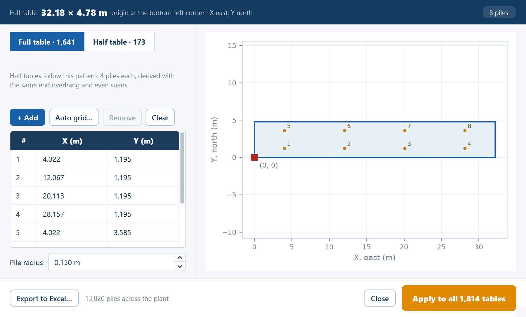
Under the switch, a status strip says where the half pattern stands. A plain line is for information; a bordered strip marks a state worth knowing; a tinted strip with an exclamation mark is a warning. The texts, with tracker for table on a tracker design:
| Side | State | Text | Button |
|---|---|---|---|
| Full | No full pattern yet | "Half tables follow this pattern once you place piles." | — |
| Full | Half pattern derived | "Half tables follow this pattern: n piles each, derived with the same end overhang and even spans." | — |
| Full | Your own half pattern | "Half tables use your own pattern: n piles each." | Review |
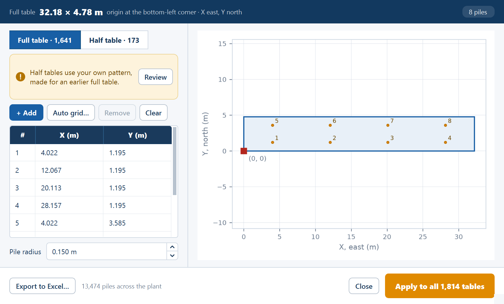
| Full | Your own half pattern, full pattern changed since (warning) | "Half tables use your own pattern, made for an earlier full table." | Review |
| Half | No full pattern yet | "Place piles on the full table first. Half tables follow it." | — |
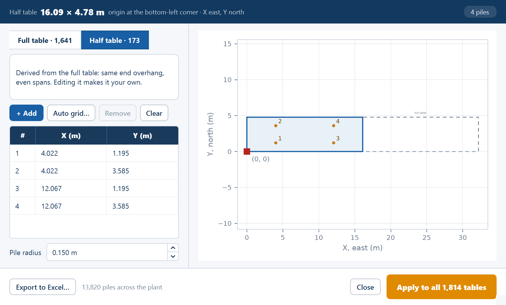
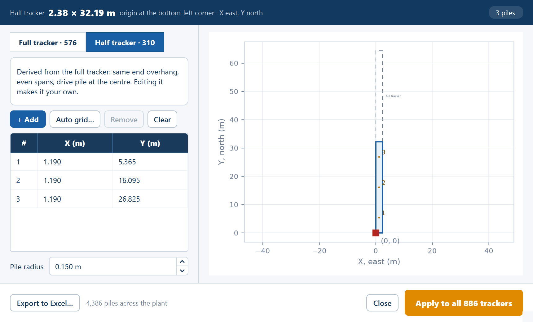
| Half | Derived | "Derived from the full table: same end overhang, even spans. Editing it makes it your own." — a tracker adds "drive pile at the centre" | — |
| Half | Your own | "Your own pattern for half tables." | Reset to derived |
| Half | Your own, full pattern changed since (warning) | "Your own pattern. The full table has changed since." | Reset to derived |
Review switches to the Half side. Reset to derived drops your own half pattern and goes back to the derived one. On the Half side the full unit is drawn dashed behind the half, labelled full table (full tracker), so you can see where the half sits against it.
The derived half pattern
Until you edit it, the half pattern is derived from the full one by a fixed rule:
- The full pattern's piles are grouped into frames along the unit's long axis — piles within 0.3 m of each other form one frame.
- The half unit keeps the full unit's end overhangs: its first frame sits where the full unit's first frame sits, and its last frame the same distance from its far end.
- Between them it gets the fewest frames for which no span is longer than the full unit's longest span, evenly spaced.
- On a tracker, one frame sits at the half tracker's centre — the drive pile — and each side of it is filled by the same rule.
- Where there is too little room, the half unit gets a single frame at its centre.
- Each frame takes its posts from the full unit's frame at the nearest relative position. Values are rounded to the millimetre.
Two examples show the rule at work. A fixed-tilt full table 20 m long, with frames at x = 1, 7, 13 and 19 m and posts at y = 0.5 and 3.5 m — 8 piles — gives its 10 m half table frames at x = 1, 5 and 9 m: 6 piles. A tracker 60 m long with piles at y = 2, 20, 40 and 58 m gives its 30 m half tracker piles at y = 2, 15 (the drive pile) and 28 m: 3 piles.
Your own half pattern
When the half unit needs something the rule does not produce — a supplier's half-table drawing, say — draw it yourself on the Half side. The first edit there makes the half pattern your own: a click in the outline, + Add, a change in the list, Remove, Clear or Auto grid… all count. From then on the half pattern stays as you drew it when the full one changes.
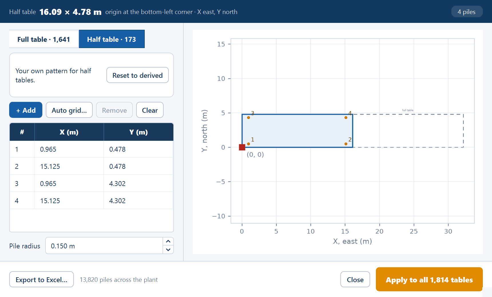
Clear on the Half side makes your own half pattern an empty one, so every half unit is left with no piles. To go back to the pattern derived from the full table, use Reset to derived instead.
With no full pattern yet, the Half side's tools are disabled: place piles on the full unit first.
When the full pattern changes
Your own half pattern remembers the full pattern it was drawn against. Change the full pattern afterwards and both sides show a warning — "Half tables use your own pattern, made for an earlier full table." on the Full side — so a half pattern drawn for an earlier table design is not carried forward unnoticed. Click Review to look at it, then keep it or use Reset to derived.
Checking the pattern against the ground
Once applied, the piles are drawn on every unit — each full unit with the full pattern, each half unit with the half pattern — with coordinate labels for the piles in view.
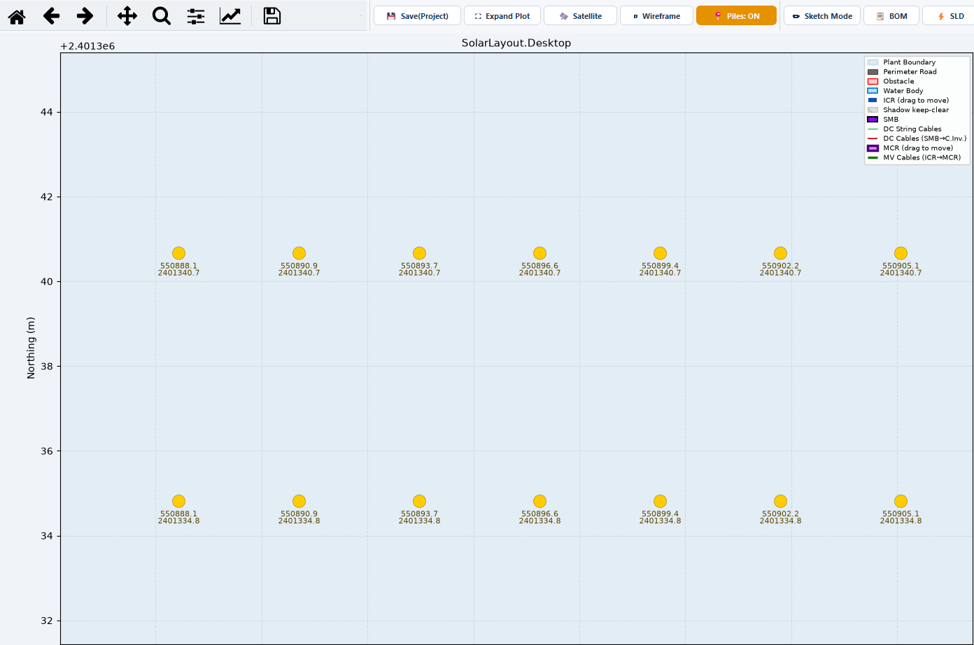

The Piles: ON overlay stays visible even with Plant layout switched off in the Layers ▾ popover. That combination — piles on, layout off — is the one to use when you are checking the pattern, because nothing is drawn except the piles themselves and their coordinates.
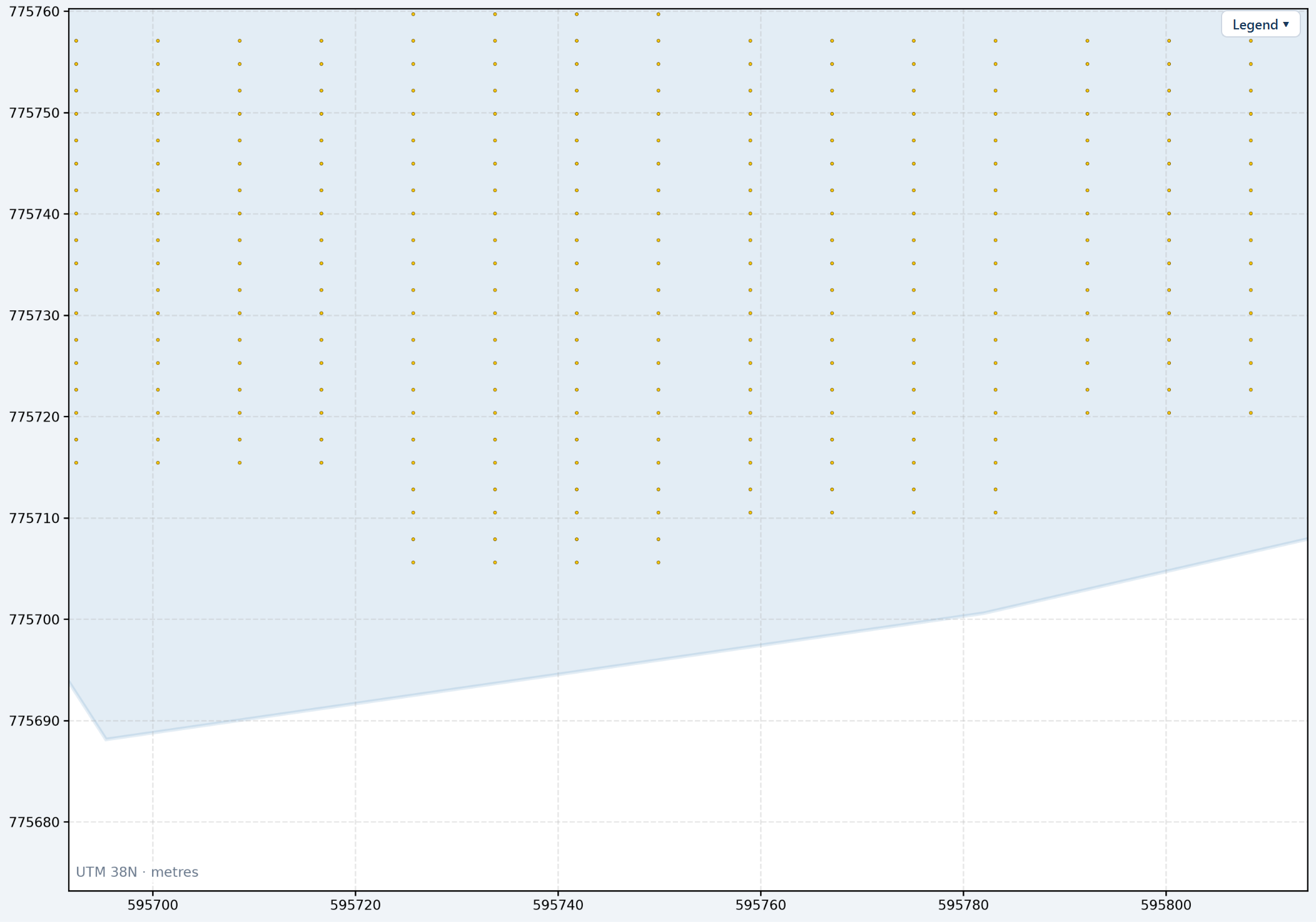
With the tables hidden you can see the pattern as a field of points and judge it the way the setting-out team does: whether the rows read cleanly, whether the spacing along the table is what the structure drawing says, whether anything lands somewhere impossible. Look along a run of half units in particular. Satellite and the Contour / terrain row have their own switches, so you can leave either behind the piles.
Patterns are part of the design
The full pattern, the half pattern and the radius are design inputs:
- They are saved in the project and come back when it is opened. The overlay's ON / OFF state is not saved.
- They survive Generate Layout and loading a new boundary file, and are applied to whatever tables the new layout has.
- Editing them does not make the layout out of date — piles are applied to the layout as it stands. See Out-of-date results.
What the Summary view reports
The Piles row of the Summary view is the plant's total pile count: each
unit counts its own piles, so it is the full units times the full pattern plus
the half units times the half pattern. The row is filled whenever a full
pattern exists, whether or not the overlay is on, and reads — until then.
Two things follow:
- Change a pattern and the total changes. Add a pile to the full pattern and the row rises by one per full table — and by whatever the derived half pattern gains on each half table.
- Change the table count and the total changes. Anything that adds or removes tables — an obstruction, an arrester footprint, a hand edit in Sketch Mode — moves the pile total with it.
The full row list is in Summary rows.
Exporting the piles
Every output that counts or draws piles counts each unit's own piles, half units with the half pattern.
| Output | When it carries piles | What it carries |
|---|---|---|
| Export to Excel…, in the Pile layout window | A full pattern exists | Every pile's coordinates, on a sheet Pile Coordinates — from the patterns in the window, applied or not |
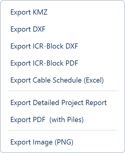
| Export ▾ Export PDF (with Piles) | The item is on the menu only while Piles is on, a pattern exists and a layout exists | The PDF report, with each unit's piles drawn and labelled on the first page and a Piles column on the summary page |
| Export ▾ Export DXF | Piles is on and a pattern exists | A PILES layer: a circle of the pile radius per pile, with its easting and northing |
| An ICR block's summary window, and Export ICR-Block PDF | A pattern exists | A Piles row per block |
| Export ICR-Block DXF | Piles is on and a pattern exists | A Piles row per block, and the PILES layer |
| The Google Earth file, the Word project report | Never | — |
A pattern alone is not enough for the CAD drawings: switch Piles on before you export them if they are to carry the piles. See CAD export and ICR blocks.
The Excel workbook
Export to Excel… opens a save dialog titled Export Pile Coordinates,
with the name pile_coordinates.xlsx suggested, and reports "Exported n pile
coordinates → …" when it is done. Its columns, in order:
| Column | What it holds |
|---|---|
| Pile ID | The pile's reference |
| Plant | The plant the pile is in |
| Table No. | The table or tracker it belongs to |
| Unit | Full or Half |
| X local (m), Y local (m) | The pile's offset in the pattern |
| Easting (m), Northing (m) | The pile's position on the ground — headed X drawing (m) and Y drawing (m) for a site placed by hand or laid out without a location |
| Longitude, Latitude | The same position in degrees; blank when the site's location is unknown |
| Pile Ø (m) | The pile diameter, twice the radius |
It needs active access, and it is refused while the layout is out of date.
Export PDF (with Piles) is the document to hand a survey or setting-out team. Its first page is drawn at 300 dpi, because a pile drawing is printed large and zoomed into on site, and its other pages are the design summary, the single-line diagram, the bill of materials and, when energy was calculated, the energy pages. See The project report.
Limits
- Nothing is checked against a structural design. Pile count, position and radius are inputs. The application draws and counts what you enter; it does not test whether the foundation works.
- Nothing is checked against the ground. The pattern is geometric, so it is applied identically on level and sloping ground. Where relief within a single table footprint matters, that is what Max height var / table in Topography is for — it governs which ground is used at all. See Topography.
- A pattern cannot vary by location. Every full unit gets the full pattern and every half unit the half pattern, so there is no way to treat the tables in one corner of the site differently.
- A later Generate keeps piles uniform on purpose. After Sketch Mode edits, Generate re-plots the aligned grid with Maximize placement switched off, precisely so that pile coordinates stay regular for construction. See Sketch Mode.
Where to go next
Annotations, measuring and layers
The drafting side of Sketch Mode — shapes, text, measurements and dimensions, the modify tools, layers and groups, the typed command line, and importing a CAD reference.
How yield is calculated
The energy model — in-plane irradiance, performance ratio, specific yield, degradation, capacity factor — the Yield tab that runs it, and the Energy view that shows the result.