Earthing design
A preliminary IEC earthing calculation for the generated layout — earth pits, GI strip and Cu cable sizes, the earthing plan, a report and a BoQ.
Earthing Design is a preliminary earthing calculation for the layout you have generated. It works out how many earth pits the plant needs and where they go, which GI strip or Cu cable size each earthing connection needs, whether the plant grid meets its resistance target and the touch-voltage limit, and what all of it adds up to as a bill of quantities. It draws the earthing plan over the plant and exports the plan, the calculation and the quantities.
The design basis is IEC. IS 3043 and IEEE 80 figures are worked out alongside as cross-checks and printed next to the IEC ones, so a reviewer working to either can see both.
Opening it
Two routes open the same window:
- Tools ▸ Earthing Design… on the menu bar. Before a layout exists it answers with Generate first — "Generate a layout first, then open Earthing Design."
- ⚡ Earthing Design, the last of the five buttons in the Studies card on the Tools tab. It is greyed out until a layout exists.
The window works on every plot of the layout that holds tables; water plots and plots with no tables are left out.
The window
Earthing Design opens beside the main window rather than in front of it, so you can keep it open while you work; it can be minimised and maximised. A verdict banner runs across the top. The inputs sit on the left in a scrolling column; the results sit on the right in three tabs, Layout, Calculation and BoQ; the exports are in the footer.
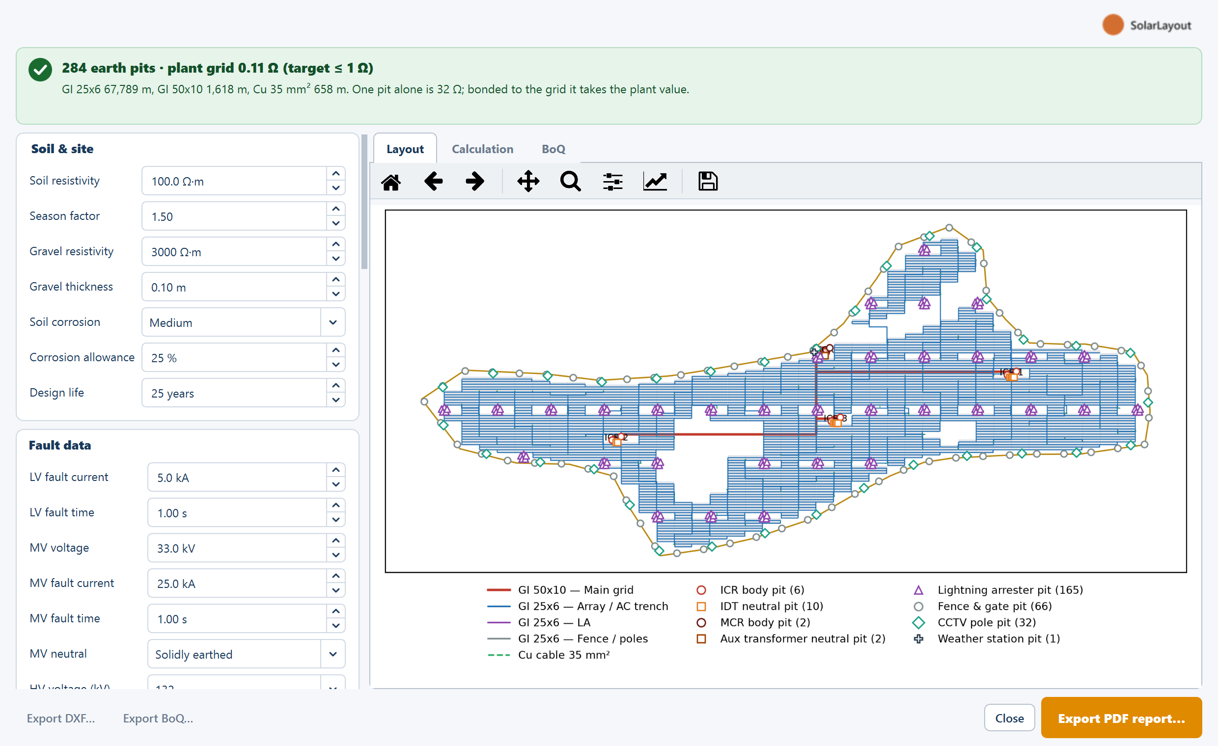
There is no Run button. The window calculates as it opens, and again a moment after you stop changing an input — about a third of a second. Every field applies to every design: fixed tilt or tracker, string or central inverter. The system frequency is taken as 50 Hz.
Inputs
Seven groups, in the order they appear.
Soil & site
| Field | Default | Range | What it does |
|---|---|---|---|
| Soil resistivity (Ω·m) | 100.0 | 1–100,000 | The measured soil resistivity, from a Wenner four-pin test. Multiplied by the season factor, it gives the design resistivity used everywhere |
| Season factor | 1.50 | 1–5 | The dry-season multiplier, for a test done in the wet season |
| Gravel resistivity (Ω·m) | 3000 | 0–100,000 | The gravel or crushed-rock layer at the ICR and MCR yards — the surface layer in the touch and step limits |
| Gravel thickness (m) | 0.10 | 0–1 | Used in the IEEE 80 surface-layer factor |
| Soil corrosion | Medium | Low / Medium / High | Sets Corrosion allowance to 15, 25 or 40 % |
| Corrosion allowance (%) | 25 | 0–200 | Extra cross-section added to every GI strip for corrosion over the design life |
| Design life (years) | 25 | 1–60 | Printed in the report |
With the defaults the design resistivity is 150 Ω·m.
Fault data
| Field | Default | Range | What it does |
|---|---|---|---|
| LV fault current (kA) | 5.0 | 0.1–200 | The inverter AC-side earth fault. Sizes the array strip and the Cu cable |
| LV fault time (s) | 1.00 | 0.05–5 | Its duration, for the same sizing |
| MV voltage (kV) | 33.0 | 1–66 | Names the main-grid duty and appears in the report |
| MV fault current (kA) | 25.0 | 0.1–200 | Sizes the main-grid strip, and is the fault current for touch and step |
| MV fault time (s) | 1.00 | 0.05–5 | Its duration, for the main-grid strip sizing |
| MV neutral | Solidly earthed | Solidly earthed / Resistance earthed (NGR) | A report label. With an NGR, enter the NGR-limited current as MV fault current |
| HV voltage (kV) | 132 | 66 / 132 / 220 | Sets HV fault current to 31.5, 40 or 50 kA |
| HV fault current (kA) | 40.0 | 0.1–200 | The HV duty, for the report only |
| HV fault time (s) | 1.00 | 0.05–5 | The same |
| Show HV in report | off | — | The design stops at the MCR; when ticked, the HV switchyard strip size is shown in the report only |
| Touch / step duration (s) | 1.00 | 0.05–5 | The fault duration used for the touch and step voltages |
| Split factor | 1.00 | 0.05–1 | The share of the MV earth-fault current that flows into the grid |
| X/R | 10.0 | up to 60 | The system X/R ratio, for the decrement factor |
Targets
| Field | Default | Range | What it does |
|---|---|---|---|
| Whole plant (Ω) | 1.00 | 0.05–50 | The plant grid target. Drives the verdict and the supplementary pits |
| Each earth pit (Ω) | 5.0 | 0.1–100 | The target for each equipment earthing point |
| LA earth pit (Ω) | 10.0 | 0.1–100 | The target for each lightning arrester's ring of pits |
| Pit rule | One pit per point, bonded to grid | or Add pits until each point meets target | How many pits each equipment point gets — see Earth pits |
Earth pit (maintenance-free)
| Field | Default | Range | What it does |
|---|---|---|---|
| Electrode length (m) | 3.0 | 1–60 | The length of each pit's electrode |
| Rod diameter (mm) | 17.2 | 5–100 | The Cu-bonded rod diameter |
| Bore diameter (mm) | 150 | 20–500 | The bore, filled with backfill compound |
| Backfill resistivity (Ω·m) | 0.20 | 0.01–50 | The backfill compound's resistivity |
| Pit spacing (m) | 6.0 | 1–50 | The spacing between pits; keep it at least twice the electrode length |
| Strip depth (m) | 0.60 | 0.3–3 | The GI strip burial depth |
Conductors
| Field | Default | Range | What it does |
|---|---|---|---|
| Initial temperature (°C) | 30 | 0–60 | The conductor temperature before a fault |
| Final temperature (°C) | 300 | 150–500 | The highest temperature of buried galvanised steel during a fault |
| GI strip sizes (mm) | 25x3, 25x6, 32x6, 40x6, 50x6, 50x10, 50x12, 65x10, 75x12 | text | The strip sizes you can buy, as width x thickness |
| Cu cable sizes (mm²) | 4, 6, 10, 16, 25, 35, 50, 70, 95, 120 | text | The Cu earthing cable sizes you can buy |
| Wastage (%) | 5 | 0–50 | Added to every strip and cable total |
The size lists take commas or semicolons, × for x, in any case. An entry
that cannot be read turns the banner to Check the size lists — "GI strip
sizes are width x thickness (e.g. 25x6, 50x10); Cu cable sizes are mm² (e.g.
16, 35)." — greys out the three exports with "Fix the inputs to export", and
leaves the results at the last calculation that worked.
Equipment rules
| Field | Default | Range | What it does |
|---|---|---|---|
| IDT per ICR (fallback) | 2 | 0–10 | Used only when the layout has no transformer grouping |
| Pits per ICR / USS | 2 | 0–8 | Pit groups at the corners of each ICR and USS ring |
| Neutral pits per IDT | 2 | 0–8 | Pit groups south of each ICR, per transformer |
| Pits for MCR | 2 | 0–8 | Pit groups at the corners of the MCR ring |
| Aux transformer at MCR | on | — | Adds auxiliary-transformer neutral pits and a body link |
| Aux TX neutral pits | 2 | 0–8 | Their number |
| Min. pits per LA | 3 | 1–12 | The smallest ring of pits round an arrester |
| Fence pit every (m) | 50 | 0–1000 | Fence pit spacing; 0 means no fence pits |
| Gates | 1 | 0–20 | One pit per gate |
| CCTV pole every (m) | 100 | 0–2000 | CCTV pole spacing; 0 means no CCTV poles |
| Weather stations | 1 | 0–10 | Pits beside the MCR |
| Serrated washers / module | 4 | 0–12 | Serrated washers per module, for frame bonding |
| Tracker bonding jumper (mm²) | 16 | 6–120 | Trackers: the flexible tinned Cu braid across each bearing and the slew drive |
| Jumper length (m) | 0.50 | 0.1–5 | The length of each jumper |
| Bearing spacing (no piles) (m) | 7.5 | 1–30 | Trackers without a pile pattern: jumpers are estimated from the tracker length at this spacing |
Layout rules
| Field | Default | Range | What it does |
|---|---|---|---|
| Strip in AC / MV trenches | on | — | Lays strip along the MV and AC cable routes and any trenches you drew. When off, or with no MV route, an L-shaped MV backbone joins each ICR ring to the USS or MCR ring |
| MMS link length (m) | 2.0 | 0–20 | Strip per MMS table, for the riser and clamp — counted, not drawn |
| Equipment link length (m) | 5.0 | 0–50 | Strip per equipment body link |
| Fence / pole link length (m) | 3.0 | 0–50 | Strip per fence, CCTV and street-light pit |
| Row runner gap split (m) | 15 | 1–200 | A row runner is broken at any gap bigger than this |
| Max cross-link length (m) | 30 | 1–200 | The longest row-to-row cross link |
What gets earthed
The network is built plot by plot:
- a GI row runner along every table row — east–west near the south edge on fixed tilt, north–south along the centre line on trackers — broken at gaps wider than Row runner gap split, with cross links between rows within Max cross-link length, and an MMS link allowance for every table;
- a Cu cable from each inverter or SMB to the nearest row runner;
- strip along the MV and AC trenches, when that option is on;
- a ring 1.5 m round each ICR, with pit groups at its corners and transformer-neutral pits south of it — the transformer count comes from the electrical grouping, or the fallback;
- USS and MCR rings with their pits, and the auxiliary-transformer pits; weather-station pits beside the MCR;
- a ring of pits round each lightning arrester;
- fence, gate, CCTV and street-light pits — local pits, not bonded to the grid and not drawn with a strip, each counted with its link allowance;
- L-shaped strips tying any isolated part of the network to the rest;
- on trackers only, a bonding jumper at each pile of the pile pattern, or estimated from the bearing spacing when there is none.
Each strip and cable total is the drawn length plus the allowances, plus Wastage. A site with several plots gets one network and one grid check per plot; the banner reports the worst.
Method and standards
| Step | Governing method | Cross-checks shown alongside |
|---|---|---|
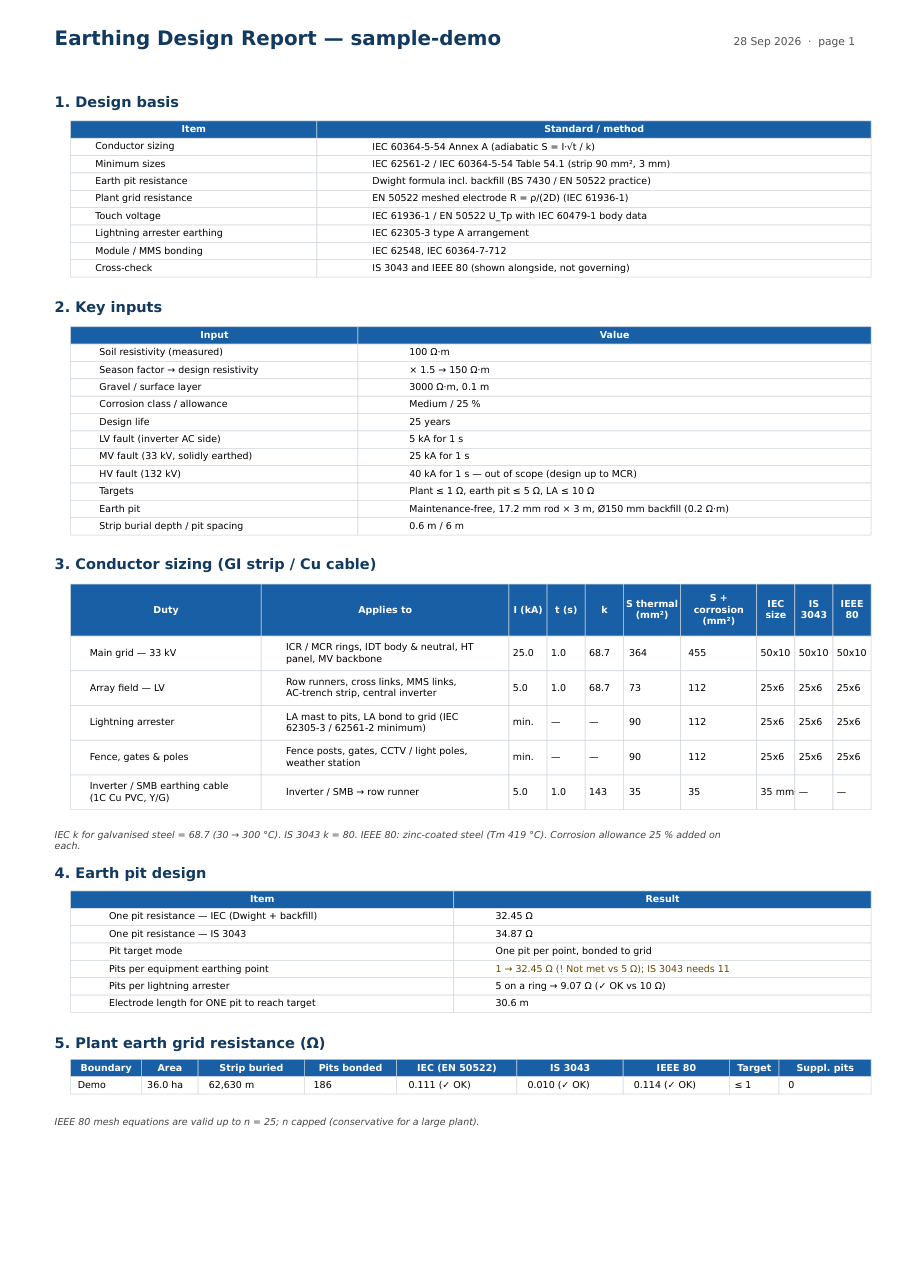
| Conductor sizing | IEC 60364-5-54 Annex A, S = I·√t / k; minimum sizes from IEC 62561-2 / IEC 60364-5-54 Table 54.1 | IS 3043, IEEE 80 |
| One earth pit | Dwight formula with the backfill column (BS 7430 / EN 50522 practice) | IS 3043 |
| Plant grid resistance | EN 50522 meshed electrode, R = ρ / (2D) (IEC 61936-1) | IS 3043, IEEE 80 |
| Touch voltage | IEC 61936-1 / EN 50522, with IEC 60479-1 body data | IEEE 80 mesh and step voltages |
| Lightning arrester earthing | IEC 62305-3, type A arrangement | — |
| Module and MMS bonding | IEC 62548, IEC 60364-7-712 | — |
Conductor sizes
Each connection is sized for its fault duty from S = I·√t / k, with k for
galvanised steel taken from the initial and final temperatures — 68.7 on the
defaults. The required area is the larger of that and 90 mm², plus the
corrosion allowance, and the strip chosen is the smallest in your list that
meets it and is at least 3 mm thick. There are four duties: Main grid
(the ICR and MCR rings, transformer bodies and neutrals, the HT panel, the MV
backbone), Array field — LV (row runners, cross links, MMS links, AC-trench
strip, central inverters), Lightning arrester, and Fence, gates &
poles — the last two at the minimum size. Show HV in report adds an HV
switchyard duty to the report only. On the defaults that gives
50x10 for the main grid and 25x6 for the rest.
The Cu cable is sized from the LV fault with k = 143 and a 6 mm² minimum, and carries no corrosion allowance — 35 mm² on the defaults. If no listed size is big enough for a duty, the report says so and asks for a larger size.
Earth pits
One pit on the defaults comes to 32.45 Ω by the IEC method (34.87 Ω by IS 3043). The Pit rule decides what happens next:
- One pit per point, bonded to grid (the default): each equipment point gets one pit, bonded to the main grid, so the whole-plant value applies at every point. When one pit alone misses Each earth pit, the report notes it and the banner adds "One pit alone is R Ω; bonded to the grid it takes the plant value."
- Add pits until each point meets target: pits are added in a line at each point until it meets Each earth pit on its own — ten pits on the defaults.
Each arrester gets a ring of at least Min. pits per LA, grown until it meets LA earth pit — five pits on the defaults. The report also gives the electrode length one pit would need to meet its target alone, and warns when the electrode is shorter than 2.5 m, the rod thinner than 15 mm, or the pit spacing less than twice the electrode length.
Plant grid and touch voltage
The IEC grid resistance depends only on the plot's area and the design resistivity: adding strip or pits does not lower it. The IEEE 80 figure does respond to the network, and the resistance carried forward is the larger of the two. When the IS 3043 or IEEE 80 figure misses Whole plant, supplementary pits are added along the array until both meet it. When the plot's area alone puts the target out of reach, no pits are added and the report says so, suggesting a grid extended outside the array (counterpoise) or soil treatment.
For touch and step, the grid current is the MV fault current × Split factor × a decrement factor from X/R and the duration; the earth potential rise is that current × the grid resistance. The IEC check passes when the earth potential rise, or failing that the mesh touch voltage, is within the permissible touch voltage — allowing for footwear and the gravel layer.
Results
The verdict banner
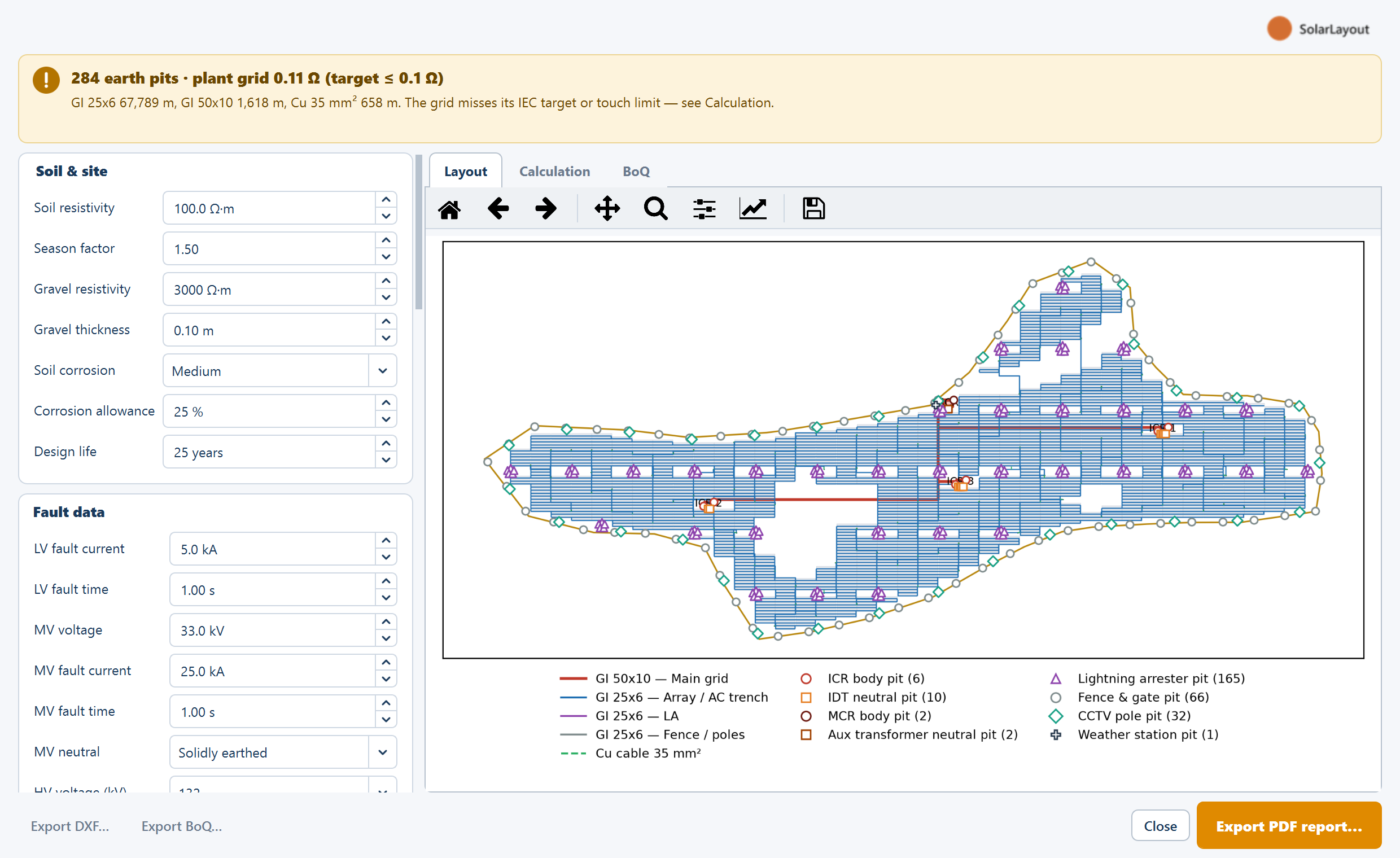
The banner reads "n earth pits · plant grid R Ω (target ≤ T Ω)", with the strip lengths by size and the Cu cable length under it. It is green when every plot meets the Whole plant target and passes the IEC touch check, and amber otherwise, adding "The grid misses its IEC target or touch limit — see Calculation." Per-point and arrester targets do not change it; they are marked in the report.
Layout
The earthing plan over the plant — boundary, tables, ICRs, the MCR and the inverters in the background — with the strips coloured by duty (main grid red, array and AC trench blue, arresters purple, fence and poles grey, Cu cable green dashed), a marker for each kind of pit, and a legend with the count of each. The plot toolbar zooms and pans it.
Calculation
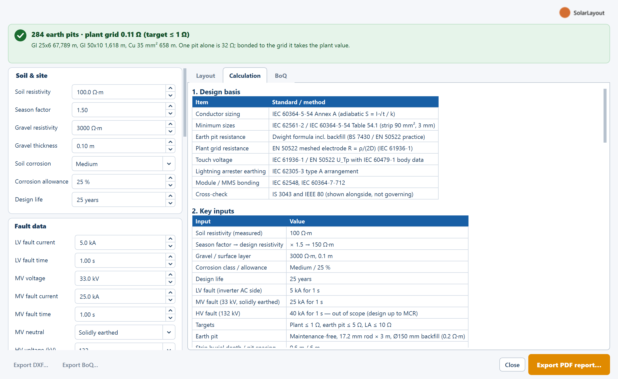
The calculation as a report, each check marked ✓ OK or ! Not met, in numbered sections: 1. Design basis, 2. Key inputs, 3. Conductor sizing (GI strip / Cu cable), 4. Earth pit design, 5. Plant earth grid resistance (Ω) (one row per plot), 6. Touch & step voltage (MV earth fault), 7. Where each earthing connection goes, 8. Earth pit count, 9. Bill of quantities, and 10. Notes when there are any.
BoQ
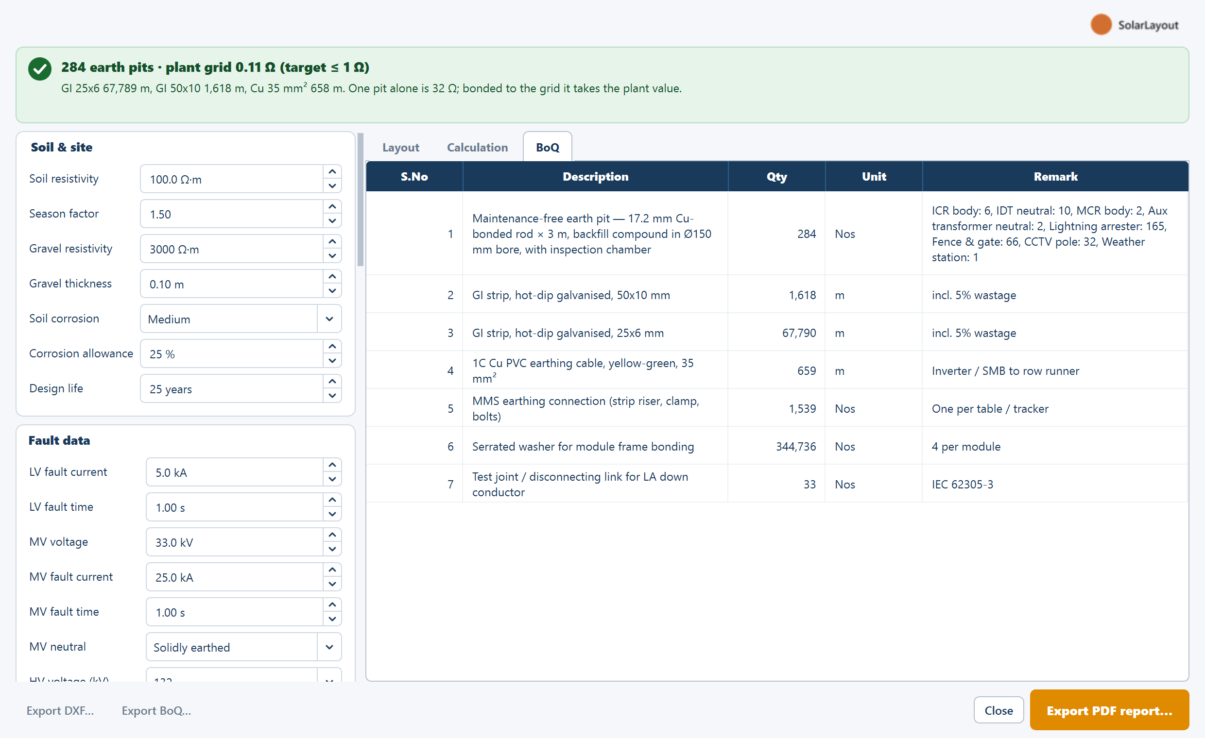
S.No · Description · Qty · Unit · Remark: the maintenance-free earth pit, with the pit count by category in the remark; one row per GI strip size, including wastage; the Cu earthing cable; the MMS earthing connections; the serrated washers; the tracker bonding jumpers, on a tracker plant; and a test joint for each arrester's down conductor.
Exports
| Button | Default file | What it holds |
|---|---|---|
| Export PDF report… | Earthing_Design.pdf | "Earthing Design Report — <project>": sections 1–10 on A4 portrait pages, then the Earthing Layout on an A3 landscape page |
| Export DXF… | Earthing_Layout.dxf | The plan in the layout's own coordinates: the layout on REF_LAYOUT, one layer per strip size and duty (such as EARTH_GI_50X10_MV, EARTH_GI_25X6_LV), one for the Cu cable, and one per kind of pit |
| Export BoQ… | Earthing_BoQ.csv | The BoQ as CSV, with the columns S.No,Description,Qty,Unit,Remark |
After a save the footer reads "Saved <path>".
How it relates to the rest of the application
- Its quantities stay in this window. Earthing materials are not in the bill of materials, the Summary, the Export ▾ menu, the layout DXF, the KMZ or the Word report. Take them from the BoQ tab and its CSV.
- Its inputs are not saved with the project. They are remembered while the application window stays open — reopening Earthing Design brings back your last values — and File ▸ New Project starts them again at the defaults. Note the values you used, or keep the PDF, which prints the key inputs.
- It works on the layout it was opened on. An open window does not follow a later Generate Layout or an edit to the layout, and is not marked out of date. After changing the layout, open Earthing Design again.
This is a preliminary design from the soil resistivity and fault levels you enter. Confirm it against a measured soil model and the actual fault study before it is issued for construction.
Where to go next
Robot count from DXF
Size a cleaning-robot fleet from any plant layout drawing, without generating a layout and without changing the open project.
Building the single-line diagram
The SLD view — the A3 drawing sheet, the Generate choice, the drawing tools, and how the finished diagram reaches the project report, a standalone PDF and a CAD file.