Building the single-line diagram
The SLD view — the A3 drawing sheet, the Generate choice, the drawing tools, and how the finished diagram reaches the project report, a standalone PDF and a CAD file.
The SLD tab (Ctrl+5) is where you draw the plant's single-line diagram — SLD, the one-line electrical schematic that shows how the modules reach the grid. The drawing sheet takes the place of the plot, and the left column hands its inputs over to the SLD TOOLS panel. You draw on a proper sheet, with a border, a zone grid, a legend band and a title block, and the finished sheet goes into the Detailed Project Report as its own page. It can also leave on its own, as a PDF or as a CAD drawing.
The diagram is a drawing, not an electrical study. The automatic build lays down a starter chain from the plant's own equipment counts, and the symbol palette carries the switchgear and instrumentation an SLD normally shows — but the ratings you print, the protection you draw and everything a grid connection needs are yours to put on the sheet.
The SLD view
Click the SLD tab, or press Ctrl+5. The right side shows the drawing sheet; the left column shows a blue banner ● SLD Preparation with an Exit SLD button, and under it the SLD TOOLS panel. The tools panel replaces the stage tabs and the Generate Layout button while the view owns the column; Exit SLD hands the column back. The view tabs and the tools beside them are described on Views.
Nothing is generated when you enter. The view shows the diagram already stored with the session, if there is one. The first row of the tools panel, Generate:, asks you to choose:
| Choice | What happens |
|---|---|
| Automatic | The diagram is built from the layout, the electrical grouping set on the ACCB & Transformer card, and the inverter file — never from the bill of materials. The status line reads "Auto-built SLD (simple feeder) — edit as needed." See Building a diagram from the plant |
| Manual | A blank sheet, for drawing from the palette. If a diagram already exists you are asked "Start a blank SLD for manual drawing? This clears the current diagram." |
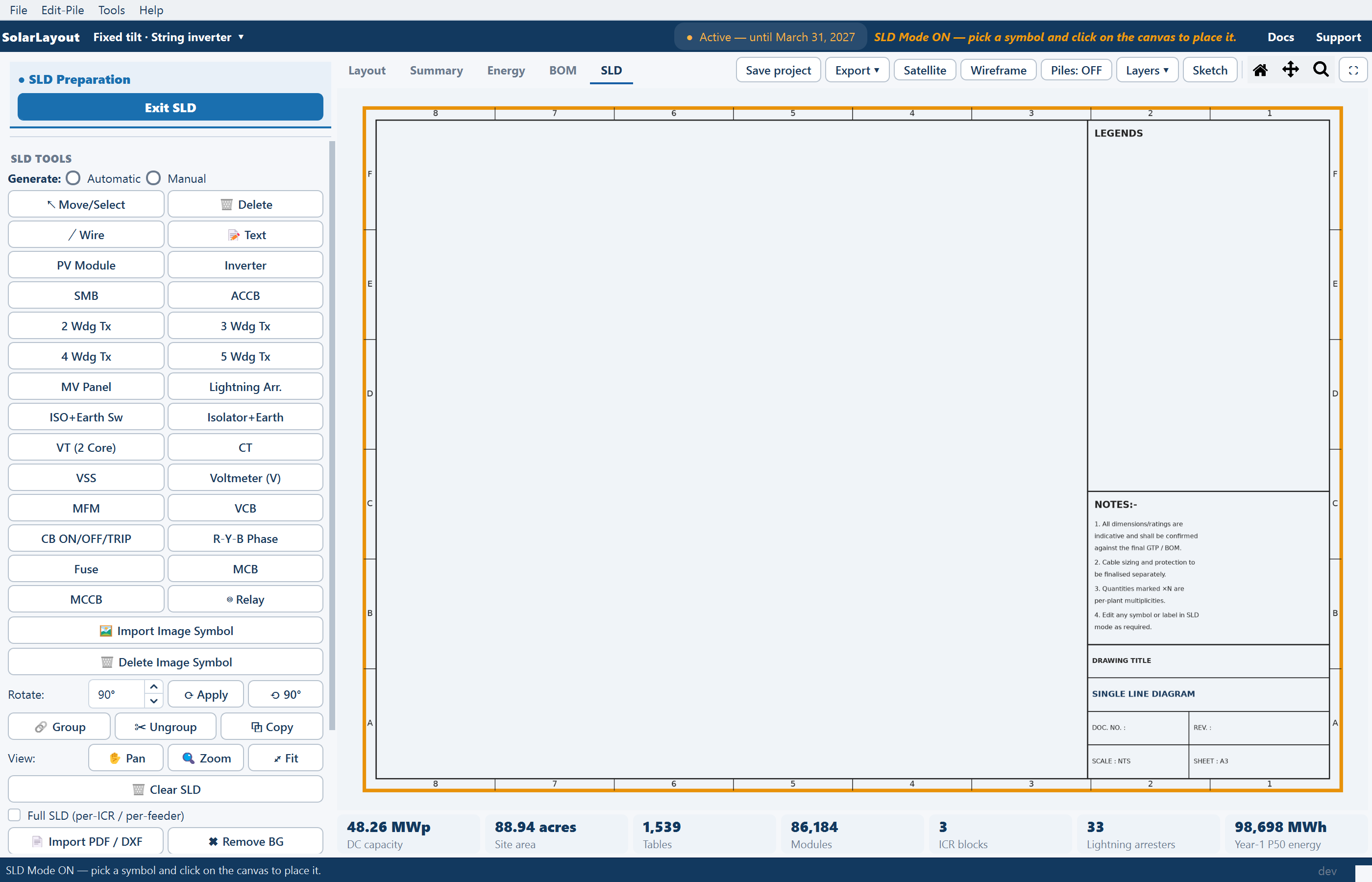
Three things are worth knowing before you choose:
- Generate the layout first if you intend to use Automatic. The automatic build reads the plant that is currently placed, so it has nothing to work from until a layout exists. The drawing tools themselves work on whatever is on the sheet.
- A stored diagram is not redrawn on its own. After a new layout, a change on the ACCB & Transformer card or a newly loaded inverter file, choose Automatic again to rebuild it.
- Tick Hide Layout & Energy Summary to gain height. The option hides the row of plant chips under the view, so the sheet gets the full height of the window. Despite its label, what it hides is the chip row, not a table. Untick it and the chips come back.
The drawing sheet
The sheet is an A3 landscape frame — 420 × 297 drawing units, the proportions of an A3 page in millimetres. Everything you place sits inside it, and the frame itself is drawn for you.
| Part of the sheet | What it is |
|---|---|
| Outer border | An orange rule around the whole sheet |
| Inner frame | The frame the drawing area sits inside |
| Zone grid | Numbers 8 down to 1 across the sheet and letters F down to A down its side, so a note or a revision can name the zone it refers to |
| LEGENDS | A panel in the right-hand band, keyed automatically to the symbols on the sheet |
| NOTES | A second panel in the right-hand band, carrying four standard notes |
| Title block | The block at the foot of the right-hand band, carrying the drawing's identity |
What the frame fills in, and what it leaves to you
The frame fills in three things for you:
- LEGENDS lists the symbols on the sheet — the automatic build's chain, or the kinds of symbol you have placed on a manual sheet — each with its symbol.
- NOTES carries four standard notes: the ratings are indicative and to be confirmed against the final GTP and BOM, cable sizing and protection are to be finalised separately, quantities marked ×N are per-plant multiplicities, and any symbol or label can be edited in the SLD view.
- The title block reads DRAWING TITLE SINGLE LINE DIAGRAM, SCALE : NTS and SHEET : with the paper size.
Nothing identifies the project, the plant or your organisation: DOC. NO. and REV. are empty, and there is no company or project name. The sheet leaves your machine as your drawing, under your own identity — write those in with the 📝 Text tool, in the same way you would label anything else on the sheet, before you export. Notes your own drawing standard requires go on the same way.
Paper size on a large plant
The automatic build's full form draws one row per combiner box or central inverter, and a plant with many of them needs more paper. The physical paper size therefore grows — A3 up to 10 feeders, A1 up to 28, A0 beyond — while the drawing box keeps A3 proportions. The simple feeder always fits A3.
The consequence is the useful part: the diagram is not re-scaled or re-flowed to fit A3. The geometry you drew is the geometry that prints, on a larger sheet. What you position at one end of the sheet stays at that end.
The drawing tools
Four tools sit at the top of the tools grid, above the symbols.
| Tool | What it does |
|---|---|
| ↖ Move/Select | Click an element to select it, then drag it to a new position. Shift-click adds to the selection |
| ╱ Wire | Click-drag to draw a connection between two points |
| 📝 Text | Click to drop a label; a label can run to several lines |
| 🗑 Delete | Click an element to remove it |
Symbols are not on this list because they come from the palette rather than a tool: click the symbol you want, then click the sheet where it goes. The full set is on Symbol reference.
Drawing a wire
╱ Wire draws the connection between two points as a click-drag: press where the run starts, release where it ends. A wire is an element in its own right, so ↖ Move/Select repositions it and 🗑 Delete removes it without disturbing the symbols at either end.
Draw the bus first and hang the symbols off it. A single-line diagram is read along its bus, and a bus drawn afterwards through symbols already placed tends to end up as a row of short segments rather than one run.
Labelling with text
📝 Text drops a label wherever you click, and a label can run to several lines — which is what makes it usable for a rating stacked under a device name, or for a title-block field with a value under its caption.
Anything you write on the sheet yourself goes on with this tool: extra notes, the title-block fields, and any annotation you want beside a symbol. Each one is an element you place, and ↖ Move/Select repositions it afterwards.
Rotating a symbol
The Rotate row acts on the current selection:
| Control | What it does |
|---|---|
| ⟲ 90° | Rotates by ninety degrees |
| the angle field and ⟳ Apply | Turns the selection to the angle in the field — 0–360°, in steps of 15°, 90° to begin with |
Ninety degrees covers most of the work on an SLD, where symbols sit either along the bus or across it. The typed angle is there for the cases that do not — an incoming line drawn at a slant, or a symbol imported from elsewhere that arrives at the wrong attitude.
The inverter and the transformers arrive already rotated
The inverter and every transformer are placed pre-rotated to 270°, so that they line up with the horizontal bus the rest of the diagram is built along. This holds in both electrical topologies — the string-inverter chain and the central-inverter chain alike.
So when you place an inverter or a transformer and it appears turned relative to its palette icon, nothing has gone wrong. It has been oriented for the bus. The symbols that are not pre-rotated are placed as drawn in the palette, and it is those you will occasionally need ⟲ 90° for.
Grouping and copying
| Control | What it does |
|---|---|
| 🔗 Group | Binds the selection into one element, so it moves as a unit |
| ✂ Ungroup | Releases a group back into its parts |
| ⧉ Copy | Duplicates the selection |
The case for grouping is repetition. A feeder bay — breaker, current transformer, voltage transformer, meter, isolator — is the same handful of symbols and wires every time. Draw it once, group it, then copy the group along the bus. Correct one bay afterwards and you can ungroup, edit, and group again.
Getting around the sheet
The View row holds three controls:
| Control | What it does |
|---|---|
| ✋ Pan | Drag the sheet under the view |
| 🔍 Zoom | Zoom into a part of the sheet |
| ⤢ Fit | Fit the whole sheet back into the view |
✋ Pan and 🔍 Zoom are switches: while one is on, a drag moves or zooms the sheet rather than editing it, so turn it off before you go back to placing and moving. The mouse wheel zooms the plot in every other view but not here — use 🔍 Zoom. ⤢ Fit is the one to reach for after a zoom, and the one to use before an export, so that you are looking at the same sheet the export will write.
Starting over
🗑 Clear SLD empties the sheet — every symbol, wire and label you have placed. The sheet frame, its zone grid, the standard notes and the title block remain, because they are the sheet rather than the drawing.
The diagram is part of the session, not a separate file. Saving the project saves the diagram with it, along with the inputs, the layout and the hand edits, and opening that project brings the diagram back as you left it. See Projects.
Building a diagram
Open the SLD view
Click the SLD tab, then tick Hide Layout & Energy Summary if the sheet needs the extra height.
Choose how to start
Choose Automatic to place the plant's own chain — modules through inverters, combiner boxes, transformers and medium-voltage panel to the grid — annotated with quantities and ratings. Choose Manual for a blank sheet if the plant is not the subject of the drawing.
Add what the chain does not carry
Place the protection, switching and instrumentation symbols your drawing standard calls for, and wire them in with ╱ Wire.
Check every rating
The automatic build annotates what it places from the electrical grouping and the inverter file. Read each annotation against the equipment you are actually buying and correct it with 📝 Text where it differs.
Complete the title block
Write the document number, the revision, the project name and anything your drawing standard adds to the notes with 📝 Text before the drawing leaves your machine.
Export
Send the sheet out as its own PDF or CAD drawing from the tools panel, or leave it to be carried into the Detailed Project Report as the report's diagram page.
The automatic build is a starting point derived from counts and grouping rules, not a protection design. Nothing on the sheet is checked against a standard, a fault level or a grid code. Read every rating and every device before the drawing goes to anyone.
Where the diagram goes
Three routes out, covered on Exporting the diagram:
- The report's diagram page. Export ▾ ▸ Export Detailed Project Report writes a Word document that carries the diagram as its Single Line Diagram annexure, on the same sheet you drew it on. The same page appears in Export PDF (with Piles) while the pile overlay is on. See The Detailed Project Report.
- A standalone PDF. ⬇ Export SLD to PDF in the tools panel — the sheet on its own, for review or for a drawing register.
- A CAD drawing. ⬇ Export SLD to DWG — the symbols written out as real
drawing entities in a
.dxffile, for a drafting team to take further.
The rest of the SLD view
Symbol reference
Every symbol in the palette and what it represents
Building a diagram from the plant
Generate: Automatic, the Full SLD option, and the grouping it draws
Importing diagrams and custom symbols
Bringing in an existing drawing, and tracing your own symbols
Exporting the diagram
The report page, a standalone PDF, and the CAD file
Earthing design
A preliminary IEC earthing calculation for the generated layout — earth pits, GI strip and Cu cable sizes, the earthing plan, a report and a BoQ.
Symbol reference
Every symbol the SLD TOOLS palette carries, grouped by what it does — generation, AC distribution, transformers, protection and instrumentation.