Robot count from DXF
Size a cleaning-robot fleet from any plant layout drawing, without generating a layout and without changing the open project.
Robot count from DXF sizes a cleaning-robot fleet from a plant layout drawing: a DXF of MMS tables or trackers, drawn here or anywhere else. It reads the tables off the drawing, groups them into cleaning lines, finds every gap between them, and counts the robots those lines need — the same count as Robotic cleaning fleet, applied to a drawing instead of a generated layout.
It needs no layout and no boundary file, and nothing is added to the current project — not to the layout, the Summary or the bill of materials. The answer lives in the window and in the PDF it exports. That makes it the tool for checking a layout from another designer, a tender drawing, or a plant already built.
Opening it
Two routes open the same window, and both work before any layout exists:
- Tools ▸ Robot count from DXF… on the menu bar.
- Robot count from DXF…, the third of the five buttons in the Studies card on the Tools tab. It is the only study there that is not greyed out before a layout.
The window opens empty, reading "No drawing open". Click Open DXF… and
pick the drawing; the file dialog takes .dxf files only. A large drawing
takes a few seconds to read.
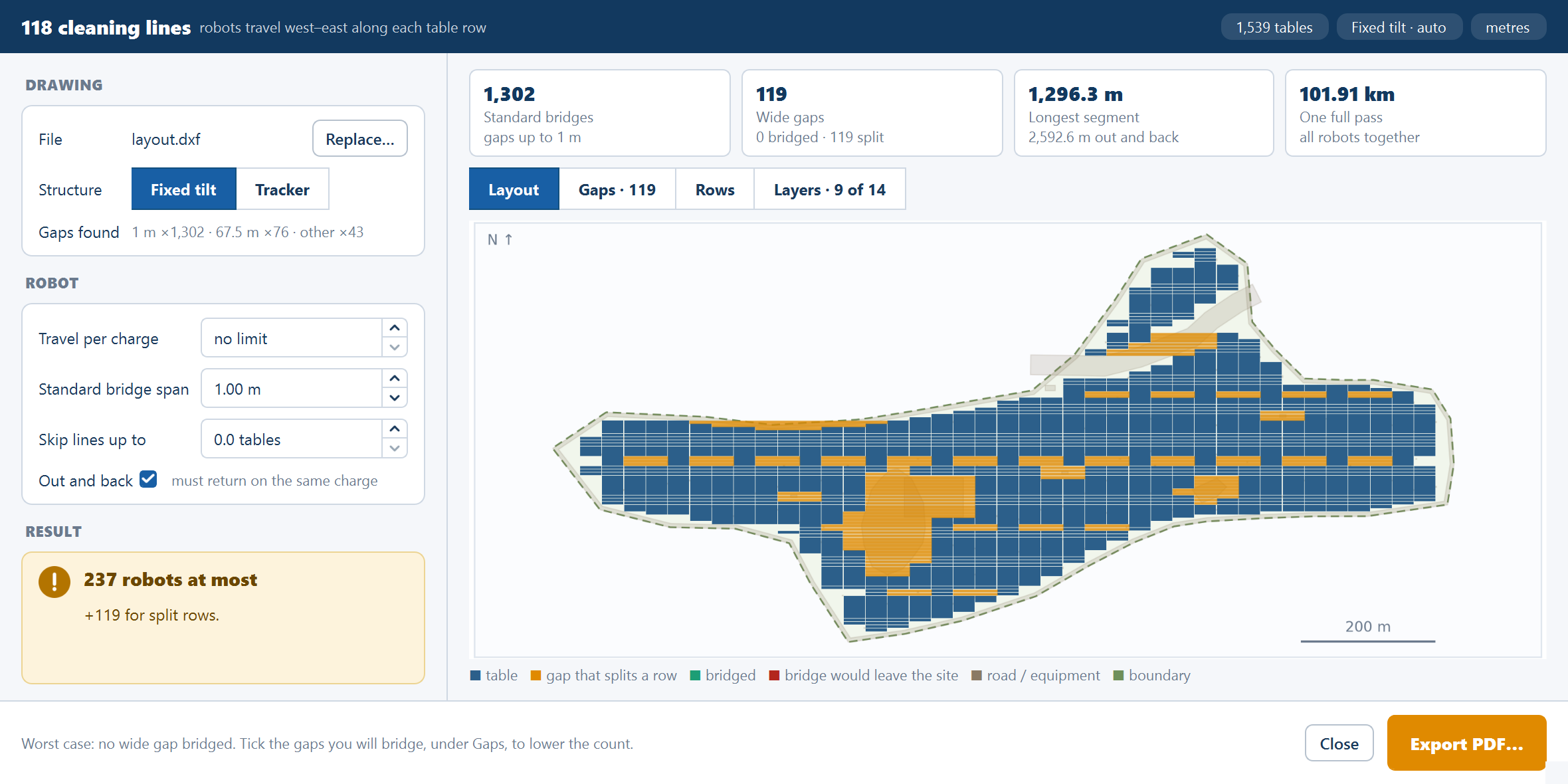
The window
Across the top a strip gives the answer's headline — n cleaning lines and the direction the robots travel, west–east along each table row on fixed tilt or north–south along each tracker column on trackers — with chips for the table count (and how many are half tables), the structure, and the unit the drawing was read in. Before a drawing is read the strip says what state the window is in: "No drawing open", "Reading drawing…", "Drawing not read" or "No tables found".
On the left sit the DRAWING and ROBOT cards and the RESULT; on the right four tiles over four views; the footer holds the export.
DRAWING
| Field | What it shows |
|---|---|
| File | The drawing's name, with Open DXF… — Replace… once one is read |
| Structure | Fixed tilt or Tracker, read from the drawing: tables whose long sides run north–south are trackers. The chip reads "· auto" until you pick one yourself. Switching it changes only the words — rows or columns — never the robot count |
| Gaps found | The gaps between neighbouring tables, the two commonest widths first and then the rest — for example 1 m ×12 · 40 m ×4 · other ×3 |
ROBOT
| Field | Default | Range | What it does |
|---|---|---|---|
| Travel per charge (m) | 0, shown as no limit | 0–100,000 | How far a robot travels on one charge. At 0 there is no battery limit and each cleaning segment gets one robot |
| Standard bridge span (m) | The drawing's commonest gap, to 0.1 m; 2.0 if the drawing has no gaps | 0–50 | The widest gap a standard bridge spans. Anything wider splits the line until you tick it under Gaps. It is reset each time a drawing is opened |
| Skip lines up to (tables or trackers) | 0 | 0–1,000, in steps of 0.5 | A line, or a segment of a broken line, carrying this many units or fewer gets no robot. A half unit counts as 0.5 |
| Out and back — must return on the same charge | ticked | — | The distance to cover is twice the segment length, so a shorter range is needed to finish a line |
A gap up to the span plus 0.25 m of placement tolerance counts as standard. Starting the span at the drawing's commonest gap means the regular spacing between tables is bridged from the start and only the unusual gaps are left for you to decide.
RESULT
The verdict banner:
| When | Headline | Detail |
|---|---|---|
| No drawing open | Open a layout DXF | "Tables as closed rectangles or one block per table, fixed tilt or tracker, in any unit." |
| Reading | Reading the drawing… | "Finding tables, layers and the boundary." |
| The file cannot be read | The drawing could not be read | "Save it as DXF from your CAD program and open it again." |
| No tables found | No tables found | "Pick the layer that holds the MMS tables under Layers." |
| Every line unbroken, no range limit reached, nothing skipped | n robots — one per row (column on trackers) | "r rows, no wide gap left unbridged." or "r rows, k wide gaps bridged." |
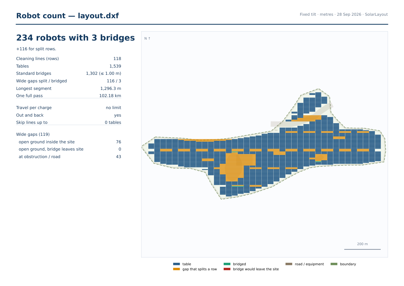
| Otherwise, with gaps ticked | n robots with k bridges | What the count is made of: "+a for split rows", "+b for battery range", "−c for skipped segments" — each only when it is not zero |
| Otherwise, nothing ticked | n robots at most | The same parts |
n robots at most is the honest starting figure: the fleet if no wide gap is bridged. The footer says so — "Worst case: no wide gap bridged. Tick the gaps you will bridge, under Gaps, to lower the count."
Tiles
| Tile | What it reports |
|---|---|
| Standard bridges | The gaps a standard bridge crosses, with "gaps up to x m" |
| Wide gaps | Every gap wider than that, as "k bridged · m split" |
| Longest segment | The longest stretch one robot serves, in metres, with "+n robots for range", its out-and-back distance, or "one way" |
| One full pass | The distance of one complete pass by the whole fleet — in km from 1,000 m up — "all robots together" |
The four views
The view tabs read Layout · Gaps · Rows · Layers, with live counts — Gaps · n, Layers · used of all. The first three need tables; Layers needs only a drawing, so a drawing in which no tables were found opens on it.
Layout
The plan in the drawing's own orientation: the boundary dashed green, roads and equipment brown, arresters red, tables navy and half tables light blue. Wide gaps are coloured by what they do to the count — gold where a gap splits a row, green where you have bridged it, red where a bridge you ticked for checking would leave the site, grey where the segment is skipped. A north arrow and a scale bar sit on the plan, and the legend lists only what is drawn. The mouse wheel zooms, dragging pans, and a double-click fits the whole drawing.
Gaps
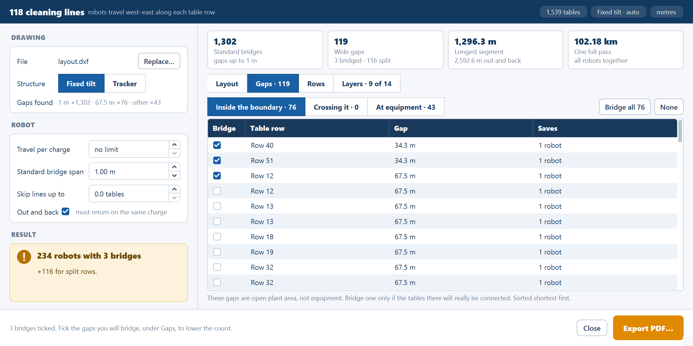
Every wide gap, one row each, works exactly as in Robotic cleaning fleet: a filter Inside the boundary · n / Crossing it · n / At equipment · n (the last only when there are such gaps); Bridge all n — Preview all n under Crossing it — and None, acting on the rows the filter shows; and the columns Bridge · Table row (Tracker column) · Gap · Saves · Blocked by, the last shown only under At equipment. Click a row to tick or untick it. Nothing is bridged unless you tick it, and a bridge that would leave the site never lowers the count.
Rows
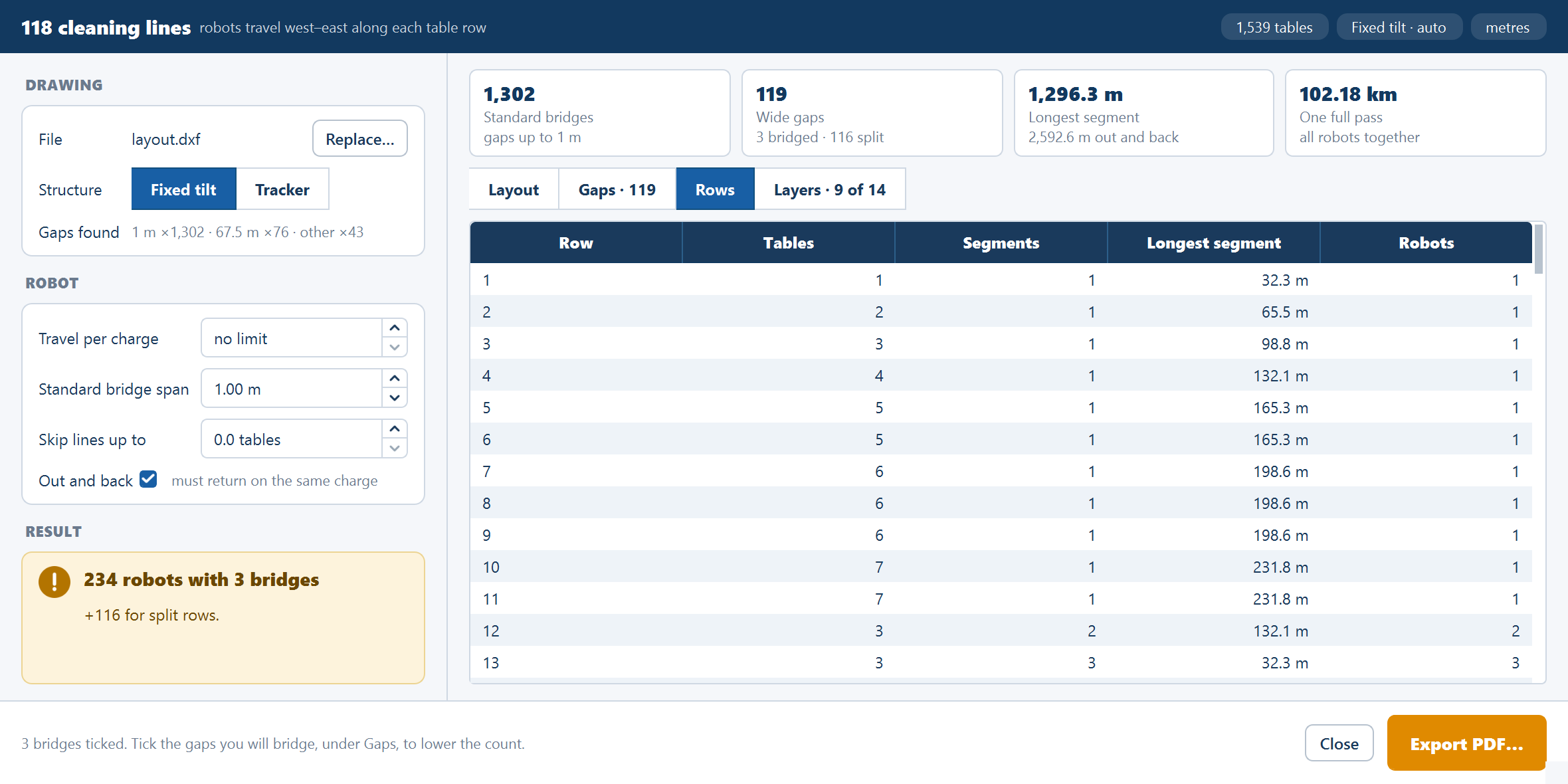
One row per cleaning line — Row (Column on trackers), Tables (Trackers), Segments, Longest segment and Robots — with a bold Total row. Use it to find the lines that carry most of the fleet.
Layers
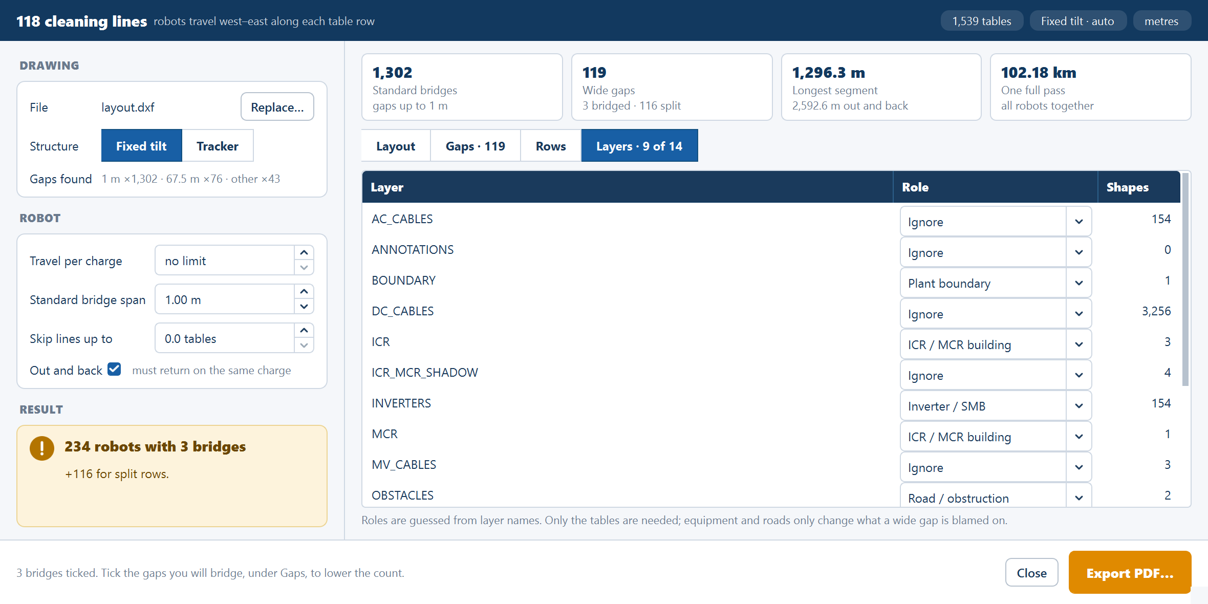
Every layer in the drawing — Layer, Role, Shapes — with the role in a list you can change:
MMS tables / trackers · Lightning arrester · ICR / MCR building · Inverter / SMB · Road / obstruction · Plant boundary · Ignore
Only the tables are needed. Equipment and roads change only what a wide gap is blamed on, and the boundary only whether a bridge is flagged as leaving the site.
How the drawing is read
Tables. A table is a closed four-corner polyline — right angles, opposite sides within 2 % — or a block insert, one per table. Arrays are expanded. Shapes more than 15 % off the commonest table width are left out, and a table drawn twice (same centre and size to 0.1 m) is counted once. A table no longer than 60 % of a full table is a half table.
Units. The drawing's own unit setting is used when it has one. Otherwise the application tries metres, millimetres, centimetres, inches, feet and kilometres in turn, and takes the first that makes a typical table between 1.5 and 300 m long. The chip in the strip names the unit it settled on.
Structure and lines. When the tables' long sides run mostly north–south the drawing is read as trackers. A drawing turned at an angle is read along its tables, so the count is the same either way. Tables are grouped into cleaning lines across the direction of travel.
What a wide gap is blamed on. The equipment shape covering at least half of the gap; failing that, an equipment or road line crossing it; failing that, Open ground. The causes read Lightning arrester, ICR building, MCR building, Inverter / SMB, Obstruction / road or Open ground; a building layer whose name contains "mcr", "substation", "pss" or "uss" gives MCR building.
Layer roles are guessed from the names
Each word of a layer name is matched from its start, and the rules are tried in this order — the first that matches sets the role:
| A word starting with | Role |
|---|---|
| text, annot, number, dim, title, label, legend, coord, grid, shadow, yard, viewport, north, logo, note, hatch, defpoint | Ignore |
| mms, table, tracker, module, panel, spv, array, or the word "pv" | MMS tables / trackers |
| bnd, bound, fenc | Plant boundary — or Ignore if the name also names a building, an inverter or a "block" |
| lightn, arrest, or the word "la" | Lightning arrester |
| icr, mcr, build, control, substation, pss, uss, css, transf, room | ICR / MCR building |
| inv, smb, scb, ajb, combin | Inverter / SMB |
| road, obstruct, obstacle, drain, nala, canal, water, pond, lake, tower, transm, keep, exclu, river, rail, pipe, or the words "tl" and "ht" | Road / obstruction |
A layer that matches none of these is tested once more by the name of the block used most on it, against the table words. Anything still unmatched is Ignore. If no layer at all comes out as tables, the layer holding the most rectangles — at least ten — is taken as the tables layer, and the note under the list says so: "The most repeated rectangles are on “<layer>” (n of them)."
When no layer looks like tables the note reads "No layer looks like MMS tables. Set the role of the layer that holds them to “MMS tables / trackers”." Set it, and the count follows.
A drawing from this application reads cleanly: its tables sit on a layer named
TABLES, its units are metres, and its boundary, arrester, control-room and
obstacle layers are recognised by name. See CAD export.
Working a drawing
Open the drawing and check what was read
Look at the strip's table count and unit, and at Gaps found. If the count is wrong or no tables were found, go to Layers and set the role of the layer that holds the tables.
Settle the structure and the layers
Confirm Structure and the layer roles before you start on the gaps, so the gap list you work through is the final one.
Set the robot
Enter Travel per charge for the robot you are pricing, and check Out and back and Standard bridge span against it. Note the n robots at most figure: the fleet with no extra bridges.
Tick the gaps you will bridge
Under Gaps, filter to Inside the boundary first — open ground, the cheaper bridges — then At equipment. Tick only the gaps you will really bridge; the verdict moves with each tick.
Export the PDF
Click Export PDF… to keep the answer. Nothing else records it.
The PDF
Export PDF… saves the robot count, the inputs, the plan and every line and
wide gap as an A4 landscape report. It is greyed out until a drawing is read and
its tables found, with the reason "Open a drawing first" or "Set the tables
layer first" beside Close. The file is offered beside the drawing, named
<drawing name> - robot count.pdf.
- Page one — "Robot count — <file>", with the structure, unit and date; the verdict; the key figures (cleaning lines, tables, standard bridges, wide gaps split and bridged, longest segment, one full pass, and the robot inputs); the wide gaps by cause; notes on how the drawing was read; and the plan.
- Cleaning lines — one row per line: tables, segments, longest segment and robots, with a total.
- Wide gaps — each gap's row, width, cause, and whether it is bridged.
The notes on page one record what was adjusted on reading: tables drawn twice and counted once, shapes on the table layers that were not table-sized and were left out, a drawing without a closed boundary (so no bridge is flagged as leaving the site), and a drawing whose tables run at an angle.
If the file is open in another program the export stops with "<file> is open in another program. Close it and export again." After a save the footer reads "Saved <file>".
Where to go next
Robotic cleaning fleet
Sizing the number of cleaning robots a plant needs, and deciding gap by gap where a supported bridge will be installed.
Earthing design
A preliminary IEC earthing calculation for the generated layout — earth pits, GI strip and Cu cable sizes, the earthing plan, a report and a BoQ.