Generating the SLD
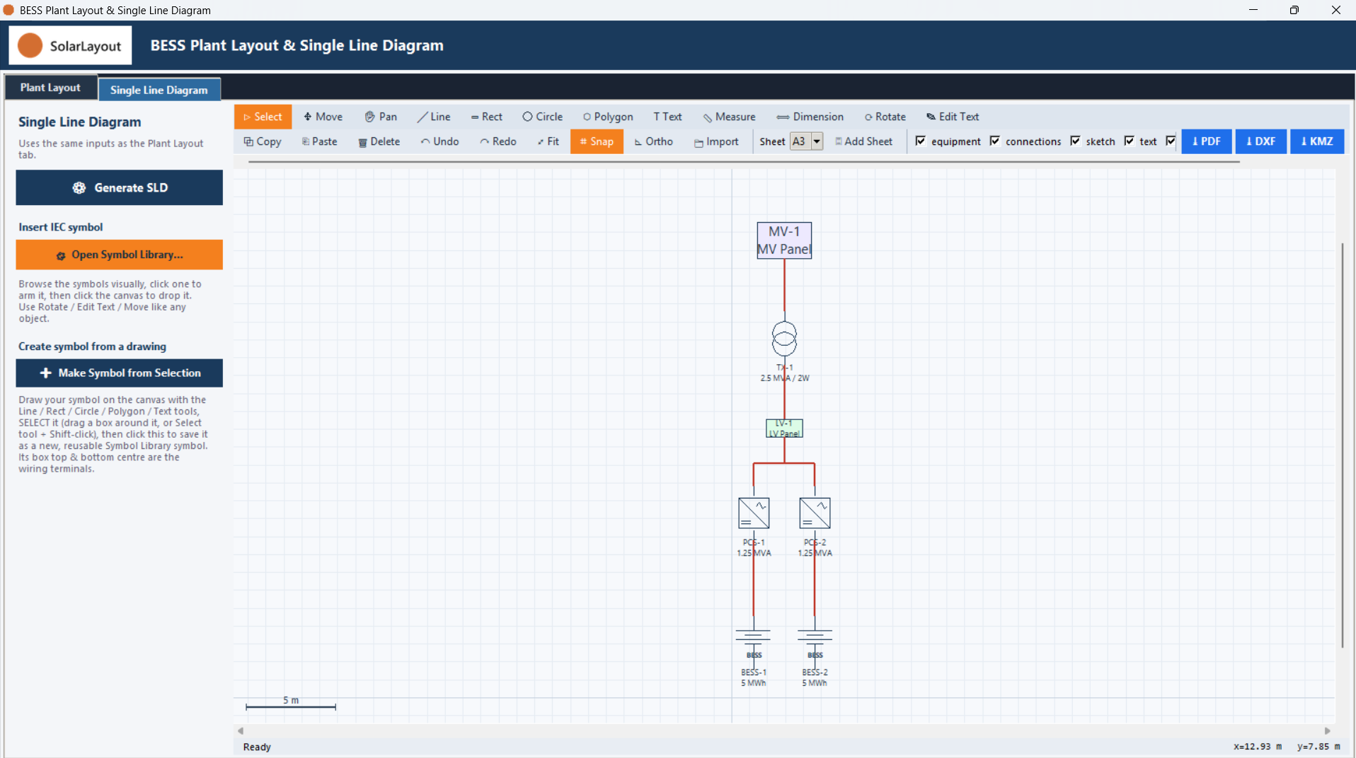
What Generate SLD draws — the same plant topology as Generate Layout, redrawn as IEC schematic symbols.
⚙ Generate SLD, on the Single Line Diagram tab, re-runs the same equipment auto-placement as ⚙ Generate Layout, then draws the result again — not as scaled rectangles this time, but as IEC schematic symbols on the same connections.
From rectangle to symbol
Each equipment type is redrawn as its own symbol:
| Equipment | Drawn as |
|---|---|
| Containers | A battery symbol |
| PCS | A PCS symbol |
| Transformer | A two-winding, three-winding or five-winding transformer symbol, matching the selected Transformer Type |
| LV panels | A rectangle at its real footprint size |
| MV panels | A rectangle at its real footprint size |
Containers, PCS and the transformer are each drawn as a fixed 3 m × 3 m symbol, regardless of the equipment's real footprint on the Plant Layout tab. LV and MV panels are not converted to symbols — they stay rectangles at their actual length and width.
Why the wires still reach
A symbol is smaller than the full-size rectangle its connections were originally routed to. To keep the wires from stopping short at the edge of that larger, no-longer-drawn rectangle, any connection that lands on a symbol's top or bottom edge is re-snapped to the symbol's own top or bottom terminal.